Understanding the Machine Definition
Introduction
The Machine Definition of the Current Settings Default dialog box is an integral part of setting up the software. The machine definition is used to define all of the elements of the machine and their parameters. The elements of the machine include the linear axes, rotary axes, and the workpiece and tool elements. When building a machine definition, you define the moving direction and limits of travel for each element. The parameters that you define in the machine definition are used in the program output. For customers with Pro Simulation/full machine simulation, geometry can be added to the machine definition to define what appears in the simulation window.
Note: The Machine Definition is used for all machine types except Lathe. The Lathe Machine Definition is currently predefined.
Elements of the Machine Tree
The machine tree contains multiple elements that are used to define the machine.
You can use the tree elements in one of two ways:
-
Click an element in the tree to display the element's parameters in the Machine Data group. The values can then be edited in the Machine Data group.
-
Right-click the element in the tree to access a shortcut menu. The shortcut menu provides options to add and remove tree elements.
Common Machine Tree Elements
-
 - this
is the top level machine element and can be thought of as the machine
base.
 -
 - this item
represents a linear axis.
 -
 - this item
represents a rotary axis.
 -
 - this item represents a revolving set.
 -
 - this items represents geometry that is added to machine elements
for full machine simulation only.
 -
 Workpiece
Transform - this item contains the stock elements that are
typically defined by each program that you create.
 -
 Toolpath
 -
 Initial
Stock
 -
 Stock
Stock -
 Fixture
 -
 Workpiece
 -
 Holder
Transform - represents the tool holder and contains items
to represent each part of the tool and holder.
 -
 Tool
- represents the tool and tool holder selected in the milling
wizard.
 -
 Flute Part - the flute of
the tool.
 -
 Shaft Part - the tool shaft.
 -
 Arbor Part - the lower half
of the tool holder.
 -
 Holder Part - the upper
half of the tool holder.
 -
 CC
- this item is the collision check. The collision check is displayed
in the Machine Data group.
Adding New Machines
When you add a new machine in the Current Settings (Default) dialog box, you can select from a predefined template or select user defined. When you select one of the provided machine templates, the template automatically creates a machine tree for the selected machine type. For many machine configurations, the order of the items in the machine tree do not need to be moved. They can however be changed if needed. You can right-click an item in the machine tree to open a shortcut menu with options to delete or add machine elements to the tree. If you use the option User Defined, the machine definition is not automatically created. If you use this method, you have to define each element to build the entire tree. You can always use a template as a starting point and then modify the template to create a custom machine configuration.
Building Machines
When building a machine, you must examine how the machine is built. For any machine configuration, you can think of the machine as having a base. The base is the foundation upon which the machine is built. Every machine element is attached to the base or to some other machine element. The relationship of all of the machine elements, how they are connected, and in which way they move, defines how the machine is built. The following sections give an example of the basic machine types and their machine tree to show the basic construction of each machine.
Warning: When selecting a component in the tree, you edit that item in the Machine Data table to the right. One of the items in the table is ID. When updating the ID of an axis, do not use spaces or numbers. If you would like to set X to an ID of X 1, you would need to enter X_one to avoid spaces and numerals.
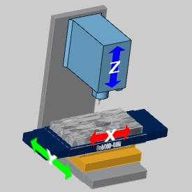
3 Axis Machines
The following example shows the BobCAD 3 Axis Mill. Notice the elements contained in the machine tree.
|
Machine Tree |
Machine |
|
|
|
The following list explains the general construction of the machine tree.
![]() Machine (Base)
- the skeleton or foundation of the machine. This is the starting point
for machine creation.
Machine (Base)
- the skeleton or foundation of the machine. This is the starting point
for machine creation.
-
 Y - attach the y-axis machine
element to the base.
 -
 X
- attach the X-axis element to the Y-axis machine element.
  Workpiece Transform -
attach the workpiece to the X-axis machine element (table).
 Z - attach the Z-axis machine element
to the base.
 Holder Transform - attach
the tool and tool holder to the Z-axis machine element (spindle).
Notice that when the Y-axis machine element moves, the X-axis and workpiece elements also move.
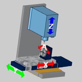
4 Axis Machines
The following example shows the BobCAD 4 Axis Mill. Notice the elements contained in the machine tree.
|
Machine Tree |
Machine |
|
|
|
The following list explains the general construction of the machine tree.
![]() Machine (Base)
- the skeleton or foundation of the machine. This is the starting point
for machine creation.
Machine (Base)
- the skeleton or foundation of the machine. This is the starting point
for machine creation.
-
 Y - attach the Y-axis machine
element to the base.
 -
 X
- attach the X-axis element to the Y-axis machine element.
 -
 A
- attach the A-axis element to the X-axis machine element (table).
  Workpiece Transform
- attach the workpiece to the A-axis machine element (rotary
table).
 Z - attach the Z-axis machine element
to the base.
 Holder Transform - attach
the tool and tool holder to the Z-axis machine element (spindle).
Notice that when the Y-axis machine element moves, the X-axis, A-axis, and workpiece elements also move.
5 Axis Machines
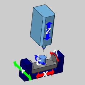
Table-Table Configuration
The following example shows the BobCAD 5 Axis Table-Table Mill. Notice the elements contained in the machine tree.
|
Machine Tree |
Machine |
|
|
|
The following list explains the general construction of the machine tree.
![]() Machine (Base)
- the skeleton or foundation of the machine. This is the starting point
for machine creation.
Machine (Base)
- the skeleton or foundation of the machine. This is the starting point
for machine creation.
-
 Y - attach the Y-axis machine
element to the base.
 -
 X
- attach the X-axis element to the Y-axis machine element.
 -
 A
- attach the A-axis element to the X-axis machine element.
  C - attach the
C-axis element to the A-axis machine element.
 Workpiece Transform
- attach the workpiece to the C-axis machine element.
 Z - attach the Z-axis machine element
to the base.
 Holder Transform - attach
the tool and tool holder to the Z-axis machine element (spindle).
Notice that when the Y-axis machine element moves, the X-axis, A-axis, C-axis, and workpiece elements also move.
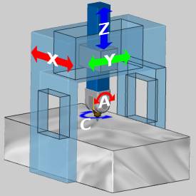
Head-Head Configuration
The following example shows the BobCAD 5 Axis Head-Head Mill. Notice the elements contained in the machine tree.
|
Machine Tree |
Machine |
|
|
|
The following list explains the general construction of the machine tree.
![]() Machine (Base)
- the skeleton or foundation of the machine. This is the starting point
for machine creation.
Machine (Base)
- the skeleton or foundation of the machine. This is the starting point
for machine creation.
-
 X - attach the X-axis machine
element to the base.
 -
 Y
- attach the Y-axis element to the X-axis machine element.
  Z - attach the Z-axis
machine element to the Y-axis machine element.
 C - attach the
C-axis element to the Z-axis machine element.
-
 A - attach the
A-axis element to the C-axis machine element.
  Holder Transform
- attach the tool and tool holder to the A-axis machine
element (spindle).
 Workpiece Transform - attach
the workpiece to the machine base.
Notice that when the X-axis machine element moves, the Y-axis, Z-axis, C-axis, A-axis, and tool holder elements also move. Also notice the workpiece transform location in the tree. For this machine, the workpiece is attached to the table (base) of the machine which is not carried by any other machine element.
Head-Table Configuration
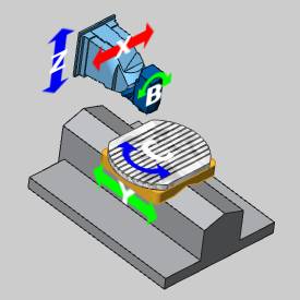
The following example shows the BobCAD 5 Axis Head-Table Mill. Notice the elements contained in the machine tree.
|
Machine Tree |
Machine |
|
|
|
The following list explains the general construction of the machine tree.
![]() Machine (Base)
- the skeleton or foundation of the machine. This is the starting point
for machine creation.
Machine (Base)
- the skeleton or foundation of the machine. This is the starting point
for machine creation.
-
 X - attach the X-axis machine
element to the base.
 -
 Z
- attach the Z-axis element to the X-axis machine element.
  B - attach the B-axis
element to the Z-axis machine element.
 Holder Transform
- attach the tool and tool holder to the B-axis machine element
(spindle).
 Y - attach the Y-axis element
to the machine base.
 C - attach the C-axis
element to the Y-axis machine element.
 Workpiece Transform -
attach the workpiece to the C-axis machine element.
Notice that when the X-axis machine element moves, the Z-axis, B-axis, and tool holder elements also move. Also, when the Y-axis machine element moves, the C-axis and workpiece elements also move.
