How to Create a Machine
Introduction
This tutorial explains how to create a machine, and will provide links to related topics.
Machine Creation
Machine creation starts with a machine definition to define each element of the machine, such as the linear and rotary axes. Then the parameters are defined for each element of the machine, such as the moving direction and limits. The parameter values defined in the Machine Definition are used when you create NC programs (G-code). For each element, geometry (.stl) files are added to define what appears in the simulation window. The geometry should only be added if you have Pro Simulation which includes the full machine simulation. The Standard Simulation does not include the full machine simulation, so the geometry files are not used. The Machine Definition must be created regardless of the simulation level. (The Pro Simulation/full machine simulation is only included with the 4 Axis Pro, 5 Axis Standard, or 5 Axis Pro modules.)
The following shows the Machine Definition tree that defines the 4-axis machine that is created in this example.
|
The Machine Definition Tree |
Machine |
|
|
|
Notice the structure of the machine tree and the machine elements. When building a machine, you must examine how the machine is built. For any machine configuration, you can think of the machine as having a base. The base is the foundation upon which the machine is built. Every machine element is attached to the base or to some other machine element. The relationship of all of the machine elements, how they are connected, and in which way they move, defines how the machine is built.
The first tree item, ![]() Machine, is labeled with the machine name.
This tree element can be thought of as the machine base. This is the starting
point for building the machine. The next machine element to define is
an element that is connected directly to the base.
Machine, is labeled with the machine name.
This tree element can be thought of as the machine base. This is the starting
point for building the machine. The next machine element to define is
an element that is connected directly to the base.
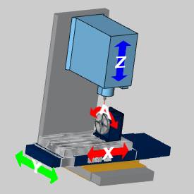
For this example, the next element defined in the tree is the linear Y-axis. This is done because it is attached to the machine base. The next machine element is the linear X-axis which is attached to, and carried by, the Y-axis element. The rotary A-axis elements are then attached to, and carried by, the X-axis element (table). The rotary table of the A-axis holds the workpiece which is the last tree item for this part/branch of the tree.
The Z-axis is separate from the elements attached to Y-axis because it is also attached directly to the machine base. The Z-axis element (spindle) holds the tool holder which holds the tool. You can see this structure in the machine definition tree. Notice that the Y-axis and Z-axis items are at the same position/priority in the tree (far left).
Steps:
Part 1) Add a New Machine
- In the CAM Tree,
right-click CAM Defaults,
and click Current Settings.
The Current Settings dialog appears.
The default page, Machine Parameters, should be active. - In the Machine
group, click Add.
The Add/Modify Machine dialog appears. - In the Add/Modify
Machine dialog, next to Machine
Name, type the name of the machine: 4
Axis Example.
Next to Type, click the arrow, and select Milling. - Next to Axes,
click the arrow, and select 4 Axis
Machine.
For all machine types except lathe, the selection made here automatically creates a template for the machine in the Machine Definition. When User Defined is selected, the Machine Definition tree is left empty for you to manually create all machine elements. (The Lathe Machine Definition is currently predefined.) - To close the dialog box and add the new machine, click
OK.
The Make list now shows the new machine is selected, and the Number of Axes box should display the number 4. - In the Machine Parameters group, define the parameters for your machine.
Part 2) Locating the Machine Definition Files
- When you create a new machine, a folder is
automatically created along with an XML file of the machine definition,
in the BobCAD-CAM Data folder. The default location is: C:\BobCAD-CAM
Data\*Current Version*\MachSim\Machine
Name.... This is the same location in which the geometry files
for the machine must be stored.
- For the purposes of this tutorial, the next
step is to copy the geometry files from the default machine that is
provided by BobCAM.
- Open the following folder: C:\BobCAD-CAM
Data\*Current Version*\MachSim.
Notice the folder named 4 Axis Example has been automatically created.
If you open the folder, you will see the 4 Axis Example.xml file that stores all of the machine information. - Open the BC_4x_Mill
folder, and select all of the files except the .xml
file. Press CTRL+C to copy
the selected files.
- Open the 4 Axis Example folder and press CTRL+V to paste the copied files into the folder.
These files are now available to add to the Machine Definition.
Important: When building your own machine, you must place the .stl files for your machine in the folder that is created by the software as explained in the previous steps.
Part 3) The Machine Definition Dialog Box - Define the Y-Axis Parameters
- On the left side of the Current
Settings dialog box, click Machine
Definition. Notice the Machine
group in the middle of the dialog. The machine tree shows all
of the machine elements that have been automatically created. This
definition includes the linear axes, the rotational axis, and the
dynamic holder and workpiece elements.
- The items in the tree are used to define
or modify the parameters of each component. For example, in the tree,
click
 Y.
Notice on the right, in the Machine
Data group, the parameters for the Y-axis display.
Y.
Notice on the right, in the Machine
Data group, the parameters for the Y-axis display.
Warning: When updating the ID of an axis, do not use spaces or numbers. If you would like to set Y to an ID of Y 1, you would need to enter Y_one to avoid spaces and numerals.
- The Direction and the Limits for the Y-axis must be defined. The machine being built requires the vector to be negative. Confirm that the Direction vector values are X0, Y-1, Z0.
Note: The vector direction for the axes is determined by the type of machine. For machines in which the table (and not the head) moves in X and Y, generally these values are negative. For machines where the head (tool) moves in X and Y, generally these values are positive. The direction is determined by the relationship of the machine elements and which way they need to move to make the tool move in a positive direction in each of the X, Y, and Z axes.
- Under Limits, to the right of Min, click in the box, and type the distance that this machine element can move along the defined direction. For this example, type -10. This defines 10 inches of travel in the negative Y-axis direction.

|

|
|
All Elements at Zero |
Negative Y-axis Limit |
- To the right of Max value, click in the box and define the maximum distance that the element can move along the defined direction. For this example, type 10. This defines 10 inches of travel in the positive Y-axis direction.
|
|

|
|
All Elements at Zero |
Positive Y-axis Limit |
-
Set the Initial Value for this element to represent the elements starting position. For this example, type 0.
This sets the initial position to the origin or zero location of the Y-axis.
Tip: You can utilize one of two methods when setting the X-axis, Y-axis, and Z-axis limits for 3-axis and 4-axis machines. In the first method you set the limits to accurately reflect the real machine. In this scenario you must properly define the Work Offset to place the part within the machine limits. Otherwise, the posting engine can fail due to the exceeded limits. You could, instead, use the second method of setting very large limits in order to not allow the posting engine to detect exceeded machine limits.
Part 4) Define the X-Axis Parameters
- In the Machine
group, click X to select the linear X-axis. In
the Machine Data group, next
to X, confirm the value is
-1.
Again, this defines that the X-axis elements must move in the negative X-axis direction in order to cause the tool to move in the positive direction in reference to the part. - Under Limits, next to Min, click in the box, and type -29.
This value defines 29 inches of travel in the negative X-axis direction.
|
|

|
|
All Elements at Zero |
Negative X-axis Limit |
- Next to Max, click in the box, and type 11.
|
|

|
|
All Elements at Zero |
Positive X-axis Limit |
-
Next to Initial Value, click in the box, and type 0.
Part 5) Define the A-Axis Parameters
- In the Machine
group, click
 A to select the rotary A-axis. In
the Machine Data group, notice
that the Direction is defined
as X1, Y0, Z0. This defines rotation
around the X-axis.
A to select the rotary A-axis. In
the Machine Data group, notice
that the Direction is defined
as X1, Y0, Z0. This defines rotation
around the X-axis. - Notice that the Centerpoint
is defined as X0, Y0, Z0.
This defines the center point of rotation in reference to the machine zero, which for this machine is the center of the front face of the rotary platter. Because the geometry was aligned to the zero of the reference point, this distance is zero. - The next step is to define the rotary limits.
Under Limits, next to Min, click in the box and type -100,000.
You must set this value to the degrees of rotation supported by the machine. - Next to
Max, click in the box and type 100,000.
- Next to Initial Value, click in the box and type 0.
Part 6) Define the Z-Axis Parameters
- In the Machine
group, click Z to select the linear Z-axis. In
the Machine Data group, notice
that the Direction is defined
as X0, Y0, Z1. This defines movement
along the Z-axis.
- Under Limits, next to Min, click in the box and type -7.
|
|

|
|
All Elements at Zero |
Negative Z-axis Limit |
- Next to Max, click in the box and type 18.
|
|

|
|
All Elements at Zero |
Positive Z-axis Limit |
-
Next to Initial Value, click in the box and type 18.
Adding Geometry to the Machine Definition (Pro Simulation Only)
Important: The Pro Simulation is included with the 4 Axis Pro, 5 Axis Standard, or 5 Axis Pro modules. If you do not have Pro Simulation, do not add geometry as shown in Parts 7-11 of this tutorial. The Standard Simulation does not include the full machine simulation, so it does not use the geometry files for simulation.
The following image shows all of the individual geometry files (.stl), together in one Workspace. This is shown to help you understand how each geometry item is aligned in the graphics area when creating the geometry files for the machine. In the second image, the view is made transparent and zoomed in to show the coordinate system used to align the machine elements.


After adding all of the geometry files to the machine definition in the following steps, the Machine tree looks similar to the following.
![]() 4 Axis Machine
4 Axis Machine
![]()
![]() mh_base
mh_base
![]()
![]() Y
Y
![]()
![]()
![]() Y Axis
Base
Y Axis
Base
![]()
![]()
![]() X Axis
Base
X Axis
Base
![]()
![]()
![]() X
X
![]()
![]()
![]() Table
Table
![]()
![]()
![]() Rotary Base
Rotary Base
![]()
![]()
![]() A
A
![]()
![]()
![]() Rotary
Table
Rotary
Table
![]()
![]()
![]() Workpiece
Transform
Workpiece
Transform
![]()
![]() Z
Z
![]()
![]()
![]() Spindle
Spindle
![]()
![]()
![]() Holder
Transform
Holder
Transform
![]()
![]()
![]() Tool
Tool
![]()
![]() CC (Collision Check)
CC (Collision Check)
Part 7) Add the Machine Base Geometry
![]() 4 Axis Machine
4 Axis Machine
![]()
![]() mh_base
mh_base
When creating geometry, the files must be saved using the .stl file extension.
- In the Machine
group, right-click the top tree item
 4
Axis Example, and click Add
Geometry.
4
Axis Example, and click Add
Geometry. - In the Open
dialog box, navigate to the 4 Axis
Example folder, and select BC_4x_Mill_Rot-X_Base.stl,
and click Open.
- The geometry item is added to the tree. In
the tree, click
 Geometry so it is selected.
In the Machine Data group, next to ID, click the name (geometry) and change the name to mh_Base.
Because the prefix (mh_) was added, the visibility of this item can be changed using the machine housing view toggle in the simulation. - Notice the remaining parameters for the geometry
item in the Machine Data group. The parameters for the added geometry
can be modified from this location. For example, if you needed to
change the .stl file, in the left column click Geometry.
Notice that the
 icon appears next to BC_4x_Mill_Rot-X_Base.stl.
You can click to
display the Open dialog box
and select a new geometry file.
icon appears next to BC_4x_Mill_Rot-X_Base.stl.
You can click to
display the Open dialog box
and select a new geometry file.
For visual reference, the base geometry file is shown next.

Part 8) Add the Y-Axis Geometry
![]()
![]() Y
Y
![]()
![]()
![]() Y Axis
Base
Y Axis
Base
![]()
![]()
![]() X Axis
Base
X Axis
Base
-
In the machine tree, right-click
Y,
and click Add Geometry. - In the Open
dialog box, select BC_4x_Mill_Rot-X_Y
Axis Base, and click Open.
- The geometry item is added to the tree. In
the tree under Y, click Geometry so it is selected.
In the Machine Data group, next to ID, select the name (geometry) and type Y Axis Base.
Warning: While adding spaces is acceptable for geometry items, it is not acceptable for the axes themselves. Both spaces and numerals must be avoided when customizing the ID of the axes. If you would like to set X to an ID of X 1, you would need to enter X_one to avoid spaces and numerals.
- Click Color,
and on the right, click .
In the Color dialog box, select
a color for the element and click OK.
When you run simulation, the Y-axis base will be shown with the selected color.
For visual reference, the Y-axis base geometry file is shown next.

- In the machine tree, right-click Y,
and click Add Geometry.
- In the Open dialog box,
select BC_4x_Mill_Rot-X_X Axis Base,
and click Open.
- The geometry item is added to the tree. Click Geometry.
In the Machine Data group, next to ID, select the name (geometry) and type X Axis Base. - Set the color used for the base.
For visual reference, the X-axis base geometry file is shown next.

Part 9) Add the X-Axis Geometry
![]()
![]() X
X
![]()
![]()
![]() Table
Table
![]()
![]()
![]() Rotary Base
Rotary Base
- In the machine tree, right-click X,
and click Add Geometry.
- In the Open
dialog box, select BC_4x_Mill_Rot-X_Table,
and click Open.
- The geometry item is added to the tree. Click
Geometry.
In the Machine Data group, next to ID, select the name (geometry) and type Table - Set the color for the element.
- Click Reflect
Map, and on the right side, click . In
the Open dialog box, select
the TableReflection.bmp file
and click OK.
Image files used for the Reflect Map must use the .bmp file extension.
For visual reference, the (X-axis) table geometry file is shown next.

- In the machine tree, right-click X,
and click Add Geometry.
- In the Open dialog box,
select BC_4x_Mill_Rot-X_Rotary_Base,
and click Open.
- The geometry item is added to the tree. Click Geometry.
In the Machine Data group, next to ID, select the name (geometry) and type Rotary Base. - Set the color for the rotary base.
For visual reference, the rotary base geometry file is shown next.

Part 10) Add the A-Axis Geometry
![]()
![]()
![]() A
A
![]()
![]()
![]() Rotary
Table
Rotary
Table
- In the machine tree, right-click A,
and click Add Geometry.
- In the Open
dialog box, select BC_4x_Mill_Rot-X_Rotary_Face,
and click Open.
- The geometry item is added to the tree. Click
Geometry.
In the Machine Data group, next to ID, select the name (geometry) and type Rotary Table. -
Set the color for the element.
For visual reference, the rotary table geometry file is shown next.

Part 11) Add the Z-Axis Geometry
![]()
![]() Z
Z
![]()
![]()
![]() Spindle
Spindle
- In the machine tree, right-click Z,
and click Add Geometry.
- In the Open
dialog box, select BC_4x_Mill_Rot-X_Z
Axis Spindle and click Open.
- The geometry item is added to the tree. Click
Geometry.
In the Machine Data group, next to ID, select the name (geometry) and type Spindle.
For visual reference, the spindle geometry file is shown next.

Part 12) About the Dynamic Elements
The dynamic elements are the elements that can change with each program. The Workpiece Transform contains the first set of dynamic elements in the tree. This transform includes the toolpath, initial stock, stock, fixture, and the workpiece. Generally, you do not have to define geometry for each of these items because they are defined by each program that you create. This is also true for the Holder Transform elements. These dynamic elements are automatically created in the tree for you when you create a new machine (except when using User Defined). The geometry for the holder element in simulation is automatically defined using the assigned tool holder from the milling wizards.
|
|
|
- In the Machine
group, under the
 Workpiece Transform, click
 Initial stock.
Notice the parameters in the Machine Data group. As with the other geometry items, you can define a color for the element. It is helpful to define a different color for each element that appears in simulation. - In the Machine
Data group, next to Transparency,
click in the box and change the value to 40.
This makes the initial stock item that is shown in simulation appear with forty-percent transparency. When this item is fully visible, it will still appear slightly transparent which makes it easier to tell it apart from the stock or workpiece items. - In the Machine
group, under the Workpiece Transform, click
 Stock.
 - In the Machine
Data group, notice the name in the Geometry
row.
For each program that you create, when you simulate, the stock.stl (and the workpiece.stl) files are automatically created and placed in the machine's folder with the other geometry files (as shown earlier in this example). These files are created using the defined stock and the selected geometry for the program. - In the Machine
group, under the Holder Transform, click
 Tool.
Tool.
Notice the parameter displayed in the Machine Data group. You can change the color for each part of the tool and tool holder, as well as the transparency and reflectivity.
Part 13) About the Collision Check
![]()
![]() CC (Collision Check)
CC (Collision Check)
At the bottom of the Machine tree, there should be an item labeled CC. This is the collision check that is automatically added to the tree when you created the new machine. This item defines the machine elements that are included in the collision check. If the items defined in the collision check do collide during simulation, the collisions are reported in the Report tab of the simulation window.
- To add a collision check to the tree, right-click
the top tree item 4 Axis Example,
point to Add CollCheck, and
click Tool-Workpiece. This
adds a collision check to the tree that is automatically set between
the workpiece and the tool.
- In the Machine
group, click the new collision check item (
 CC1).
CC1).
Notice the information in the Machine Data group. There are three boxes displayed. The larger box on the left side contains all of the items that are available to add to a collision check group. The two boxes on the right, Group 1 and Group 2, define the items that are collision checked. Any items in Group 1 are collision checked with the items in Group 2. The Workpiece-Tool collision check that was added automatically places the Workpiece in Group 1 and the Tool is placed in Group 2. - To add an item to a collision check group,
in the list on the left side, click the item to add. Next to the Group box to which the item is added,
click
 .
. - To remove an item from a collision check,
click the item to remove, and then next to the Group
box, click
 .
. - If you add a User Defined collision check, no items are automatically added to the Group 1 and Group 2 boxes.
Save the Machine
- To finish the machine creation and save the information, at the bottom of the Current Settings dialog, click OK.
Understand that you click OK to save the information in the dialog box, but there is more information to define. The remaining pages of the Current Settings dialog must also be defined in addition to the Machine Definition.
Part 14) Additional Machine Parameters
After your machine has been created, you also need to define the Posting parameters for the machine. To learn about the remaining options in the Current Settings dialog box, view the Current Settings Default.
This concludes the tutorial.