 Patterns
Introduction
This topic explains the options found in the Patterns page of the Facing operation in the Mill 2 Axis Wizard, and will provide links to related topics.
The Patterns page
Patterns
-
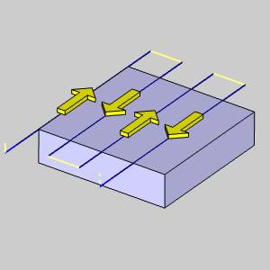
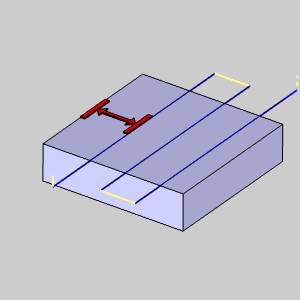
 Zig Zag - defines a two-way
or alternating cutting pattern.
Zig Zag - defines a two-way
or alternating cutting pattern.
-
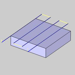
 Zig - defines a one-way cutting
pattern with retracts between each path.
Zig - defines a one-way cutting
pattern with retracts between each path.

-
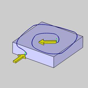
Adaptive - defines a high-speed
machining operation with automatic tool engagement settings. In
addition, the Link Clearance is added to the Finish group in the Parameters
page of the wizard.
-
Off Workpiece - allows
the toolpath to continue past the bounds of the part and enables the
Distance box.

- Distance - type a value to set how far the tool travels off of the stock. This is the distance from the edge of the tool to the edge of the stock/part.
-
On Workpiece - keeps the
toolpath contained within the bounds of the part and enables the Distance
(% of Tool Diameter) box.

- Distance (% of Tool Diameter) - type a value, that is a percentage of the tool diameter, used with the On Workpiece setting.
Cut Directions
Select the cutting direction for the operation
as X Direction, Y
Direction, or Custom. This section is not available when the Adaptive Pattern is selected.
-
X Direction - will align the passes
parallel to the X axis of the Machine Setup.
-
Y Direction - will align the passes
parallel to the Y axis of the Machine Setup.
-
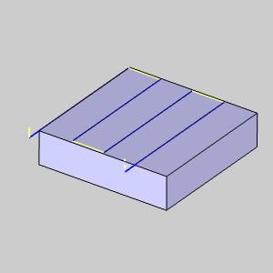
Custom
- will align the passes according to a custom value entered.
- Angle
- defines the angle (from the X-axis) of the toolpath when using
the Custom option.
- Angle
- defines the angle (from the X-axis) of the toolpath when using
the Custom option.
- Start Position - select a corner of the option box to define the starting position of the operation.
Direction
When the Custom Cut Direction is selected you can choose between the following:
-
Climb Mill - the tool travels
in a counter clockwise direction along the inside shapes of the model
and travels in a clockwise direction along the outside edges of the
model.
-
Conventional Mill- the tool travels
in a clockwise direction along the outside edges of the model.
Parameters
-
Stepover (% of Tool Dia) - set the stepover value based on a percentage of the selected tool size.

-
First Cut Offset - sets an offset value used for the first cut of the feature.
 MDI (Manual Data
Input)
MDI (Manual Data
Input)
View the MDI topic.
Related Topics
Clicking Next> > takes
you to the next page of the Mill 2 Axis Wizard. To move to the corresponding
topic, click the appropriate link below.
The Profile Rough Parameters
page
The Profile Finish Parameters page
The Pocket Parameters page
The Facing Parameters page
The Engrave Parameters page
The Chamfer Mill Parameters
page
The Plunge Rough Parameters page
The Corner Rounding Parameters page