Tool Axis Control
Introduction
This topic explains the Tool Axis Control page of the Mill 3 Axis Wizard, the options found in it, and will provide a link to an example.
Tool Axis Control
Method
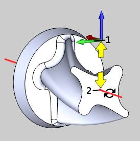
This group controls the number of axis used for the operation. Choose between 3, 4, and 5 Axis.
Important: As it pertains to outputting the NC code: When using the 3 Axis option we will use the setting listed for the Standard option in the Move List Coordinates group of the Multiaxis Posting page of the Current Settings dialog. When 4 or 5 Axis is used, we will use the setting listed for Multiaxis Simultaneous Motion of the same group.
Parameters
This group becomes available when using the 4 and 5 Axis method.
-
Max Angle Step
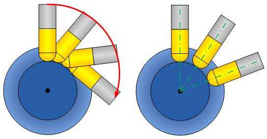
This option determines the maximum angle step, or amount or rotation, applied to rotation axis movements between toolpath points. Select the check box to turn on the option and then type the angle value in the box. Any machine movement beyond this angle is reduced by adding more toolpath points to smoothen the machine movements as a division of the angle change and maximum angle step. This is provided to reduce or eliminate abrupt machine movements, specifically for some machine controllers that do not limit large rotation changes, which can break tools or gouge surfaces.
Rotary Axis
You must select the Rotary Axis being used for the feature, which includes the Direction and the Base Point.
Important: The Rotary Axis Direction and Base Point parameters are used for the toolpath creation and are not necessarily the same as the machine's rotary axis.
Select the proper axis for the part orientation:
-
X Axis - Rotation around the X Axis.
-
Y Axis - Rotation around the Y Axis.
-
Z Axis - Rotation around the Z Axis.
-
User Defined - Rotation to be defined manually with the Direction values below.
-
 - opens the Re/Select Geometry dialog to allow you to define the location of the Rotary Axis.
 -
Method - Choose between Pick a line, or Pick two points. The Selected Geometry group will then allow you to select a line, or a Start Point and an End Point.
-
-
Point Tool to Rotary Axis
![]() Select the check box to force the tool axis to point at the defined rotary
axis of the part.
Select the check box to force the tool axis to point at the defined rotary
axis of the part.
![]() Clear the check box to turn off this option.
Clear the check box to turn off this option.

-
Direction - displays the direction vector for the selected rotary axis. The XYZ values are automatically updated when you select X Axis, Y Axis, or Z Axis. For example, rotation around the X-axis is defined by the vector X1Y0Z0. When selecting User Defined, the Direction XYZ values become available for you to define a custom rotary axis direction vector.
-
Base Point - is used to define the distance from the Machine Setup (machining origin) to the rotary axis of the part. If the Machine setup is aligned with the rotary axis of the part, the Base Point values should be X0Y0Z0 (for most scenarios). As another example, if you set the Machine Setup to the top of a four-inch cylinder, you define the Base Point as X0Y0Z-2.

- 5th Axis
These options are only available with the 5 Axis Standard, or the 5 Axis Pro modules. Locked at Angle - is used
to lock the 5th axis to a fixed angle.
 Relative to Cutting Direction - provides a fixed
tilting angle relative to the toolpath cutting direction. This setting
forces the Point Tool to Rotary Axis parameter.
Relative to Cutting Direction - provides a fixed
tilting angle relative to the toolpath cutting direction. This setting
forces the Point Tool to Rotary Axis parameter.- Angle
- type the tilt angle for the selected 5th axis parameter.
- Angle
- type the tilt angle for the selected 5th axis parameter.
Note: For more information about the toolpath output, view Output Format.
