How to Convert a 3 Axis Feature to 5 Axis
Introduction
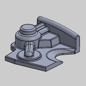
This tutorial explains how to create a 5 Axis operation from existing 3 Axis toolpath.
Example File
The SolidWorks part file for this tutorial is available for download at: http://www.bobcad.com/helpfiles. If you are connected to the Internet, you can click the link provided to download and save the 3 to 5 Axis Conversion Example 1.SLDPRT zip file. After extracting the zip file, you can then open the example file to use with this tutorial. In the example file provided, the Tool Crib is already equipped with the necessary tools and the stock and Machine Setup are already defined. The part is simulated using the BC_Hermie_C20U machine.
Note: In this file you will also notice the first feature is set not to post. This is to save time launching the simulation. The first feature has been simulated, the resulting stock has been saved as an stl and then applied as the stock for the job.
In this example, you adjust an existing toolpath in order to finish the remainder of the part with a short tool.
Part 1) Simulation
For more help using simulation, view Getting Started with Simulation.
-
To view the program, in the Quick access menu of the CAM Tree, click
 Simulation.
 -
In the Analysis tab, with the option set to Deviation, click
 Min/Max Detection, and then
  Refresh Cutsim to view the deviation report.
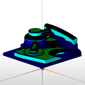
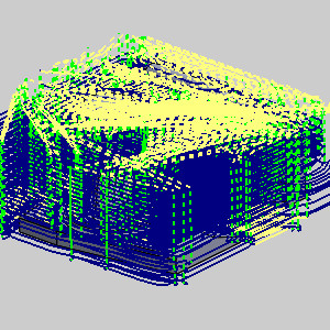
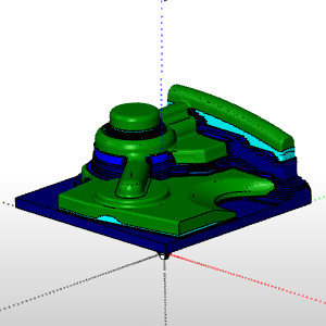
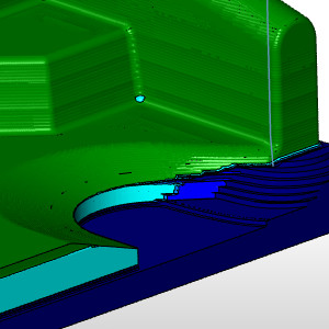
This is where the first two operations left the stock. If we were to have simulated the first two operations from the original rectangular stock we would have seen: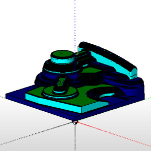
-
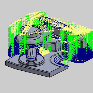
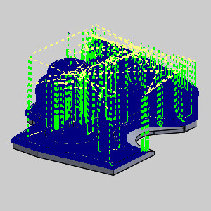
Click Play to view the current operation.
Notice the Arbor and Holder gouge a good portion of the stock. -
To close simulation, in the
 Exit Simulation.
 -
The simulation shows no issues on this feature, so in the CAM Tree, right-click Finishing, and click Blank/Unblank Toolpath.
-
Click the arrow next to the feature to collapse it.
Part 2) Edit the Feature
-
In the CAM Tree, click each operation to view the toolpath.
-
In the CAM Tree, right-click Finishing and click Edit.
-
In the Mill 3 Axis Wizard, click Gouge Check in the tree on the left.
-
Select the check box for the Check 1 group.
-
In the Geometry section, select the check box for Feature Geometry.
This tells the gouge check to use the selected feature geometry as the check surfaces. -
In the Check Tool section, select the Tool and Holder radio button.
This tells the gouge check to ensure neither the Tool nor the Holder gouge the selected surfaces. -
In the Strategy section, select Trim and Relink and leave its option to Trim collision only.
This tells the gouge check to trim and portions of toolpath that cause a gouge and relink the created gaps. -
At the bottom of the page, click Clearances for tool parts.
The Tool Clearances dialog appears. -
In the Clearance values group, set the Arbor and Holder values to 0.2000.
-
Click OK.
-
Click Compute.
Part 3) Simulation
For more help using simulation, view Getting Started with Simulation.
-
To view the program, in the Quick access menu of the CAM Tree, click
Simulation. -
Click
Refresh Cutsim to view the deviation report. -
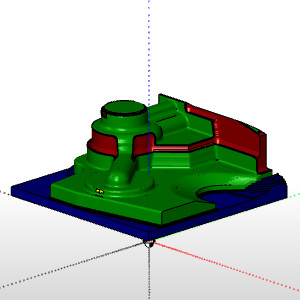
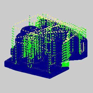
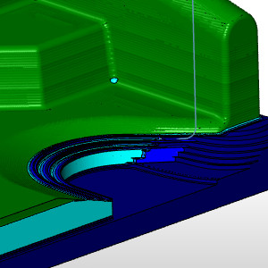
Click Play to view the current operation.
Notice the Arbor and Holder no longer gouge, but the lower part of the walls cannot be finished. -
To close simulation, in the
Exit Simulation.
Part 4) Setting the Tool Axis Control
-
Right-click the Finishing feature and select Edit.
-
Click Tool Axis Control in the tree on the left.
-
Set the Method to 5 Axis.
-
Click Gouge Check in the tree on the left.
-
In the Strategy section of the Check 1 group, change Trim and Relink to Tilt Tool.
-
Click Compute.
Part 5) Simulation
-
To view the program, in the Quick access menu of the CAM Tree, click
Simulation. -
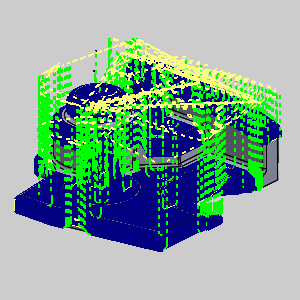
Make sure collision reporting is on and click Play to view the current operation.
Notice the collision that occurs.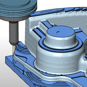
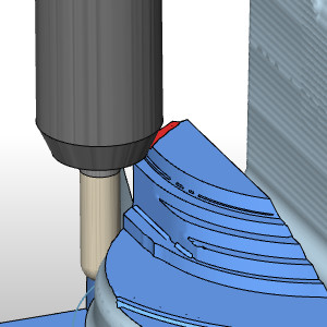
The underside of this part will finished with facing operations, and since the fillet is already complete, we can prevent this gouge by limiting the depth of the operation. -
To close simulation, in the
Exit Simulation.
Part 6) Set Bottom of Job
-
Edit the feature and click Parameters to get to the Depth Options.
-
Select the check box for Bottom of Job.
-
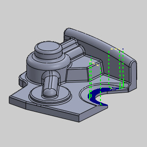
Click the Pick button that appears.
The Mill 3 Axis Wizard disappears and the -
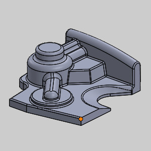
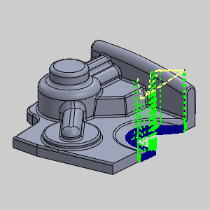
Select the bottom of the fillet as seen in the image below.
-
Click OK.
The Mill 3 Axis Wizard returns. -
Behind the value in the Bottom of Job text box, enter -0.125 and press Tab.
The value updates. Our tool should now stop directly below the completed depth of the fillet. -
Click Compute.
Part 7) Simulation
-
To view the program, in the Quick access menu of the CAM Tree, click
Simulation. -
Click
Refresh Cutsim to view the deviation report. -
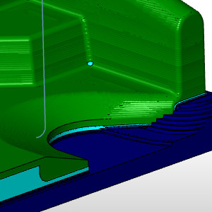
Click Play to view the current operation.
Notice the only issue left is the area not completed due to the depth limit on the operation. -
To close simulation, in the
Exit Simulation.
Part 8) Create secondary feature
-
Right-click the Finishing feature and select Copy with Geometry.
-
Right-click the Finishing feature and select Paste.
-
Edit the pasted feature and click Parameters to update the Depth Options.
-
Copy the value from the Bottom of Job.
-
Clear the check box for Bottom of Job.
-
Select the check box for Top of Job and paste the value in.
-
Click Finish.
-
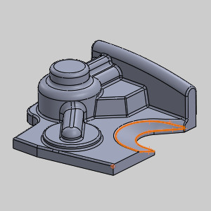
In the CAM Tree, expand the new feature, right-click Boundary and select Re/Select.
The -
Select the following geometry and click OK.
-
Right-click the feature and select Compute All Toolpath.
Part 9) Simulation
For more help using simulation, view Getting Started with Simulation.
-
To view the program, in the Quick access menu of the CAM Tree, click
Simulation. -
Click Play to view the Roughing operation in simulation.
-
To close simulation, in the
Exit Simulation.
Part 10) Edit the feature
-
Right-click the feature and select Edit.
-
Click Options.
-
In the Boundary Options section of the Limits group, select Tool Outside.
-
Click Compute.
Part 11) Simulation
-
To view the program, in the Quick access menu of the CAM Tree, click
Simulation. -
Click Play to view the Finishing operation in simulation.
Notice we have completed the ramped area. The rest of the excess material would be handled in the operations coming from the other side of the part, which this example does not need to cover. -
To close simulation, in the
Exit Simulation.
This concludes the example.