Cuts Along Curve
Introduction
The Cuts Along Curve feature allows you to create a toolpath perpendicular to a Lead curve (drive curve) on a selected Drive Surface. If the curve is a straight line, then the cuts are created parallel to each other. You can use a surface edge as the Lead Curve, or a curve that is on the surface. If the curve is not on the surface then it is projected onto the Drive surface to create the toolpath.

Surface Paths
Pattern
Edit curves
-
Lead - enables selection mode for you to select the Lead curve geometry. The toolpath is applied perpendicular to the selected curve, but on the selected drive surfaces.
-
Drive surfaces - enables selection mode for you to select the Drive Surfaces geometry. The toolpath is applied to the selected surfaces.
-
Drive surfaces offset - is used to leave stock remaining on the part. You can use positive or negative values.
To learn about the remaining Surface Paths parameters, view Surface Paths.
To learn about the other Multiaxis Parameters, view the Multiaxis Wizard.
How It Works
-
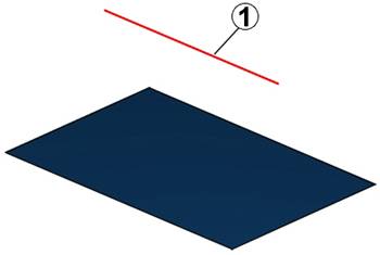
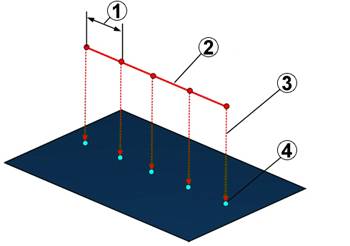
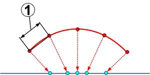
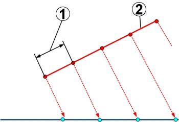
Take a surface with a curve above (1). The curve, in this case a simple line, is parallel to the drive surface.
-
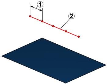
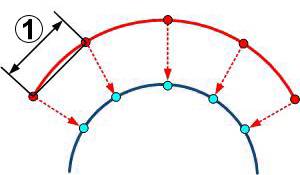
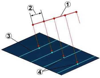
Now the system generates virtual points on the curve (2). The distance between those points (1) is the maximum step over value.
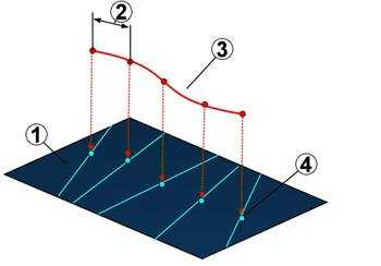
-
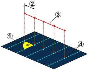
These points are projected to the drive surface (4). The direction of the projection is the normal vector from the point on the curve to the surface (3). A virtual surface point is created where the normal vector intersects the drive surface.
-
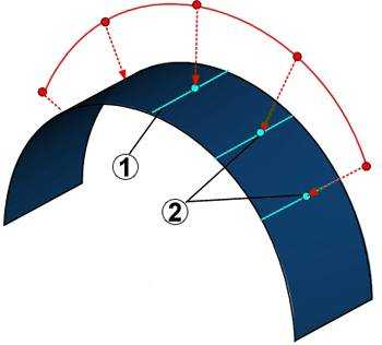
Toolpath is generated perpendicular to drive curve from projected points on drive surface (1).
Examples
-
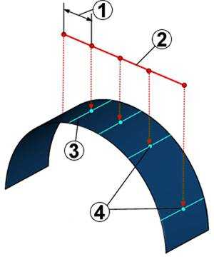
Curved surface with a line as curve.
-
Flat surface with a curve above.
-
Curved surface with a curve above (same radius).
-
Flat surface with a line as tilt curve above (tilted).
-
Flat surface with plane parallel curve.
-
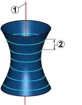
Line through cylinder (parallel to cylinder center).
-
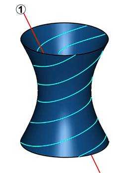
Line through cylinder (tilted).
-
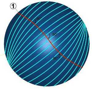
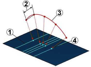
In this example you can see the generated toolpath is orthogonal to the leading curve (1). It’s important that the toolpaths don’t cross each other at the edge of the drive surface. Here the cuts just come very close to each other.