Link: Multiblade
Introduction
This topic will explain the options found in the Link tab of the Multiblade operation.
Link
The Link tab allows you to control the links between cuts and slices, clearances, distances, home position, and will allow you to set a rapid feed rate as well as apply a link smoothing value.
Links between cuts/slices
- Automatic
The automatic linking uses preset for the linking between the layers and slice. In case the user uncheck the automatic linking it is possible to manually set the link types. All links are collision checked. In case a link would collide, the system internally changes either the link type or the distance parameter. - With this check box selected, the system handles which links to use between cuts.
 - With this check box cleared, the user is able to specify which links to use between cuts.
 - Use
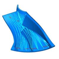
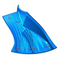
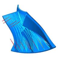
- Direct blend - combines the Direct line and Blend spline option in order to stay closer to the part. With these options selected the lead options are unavailable.
- Direct line - moves uses a straight line to connect the end of one cut with the beginning of the next.

- Blend spline - uses a tangential connection to end one cut and begin the next.

- Feed distance - uses a small retraction along the tool axis and steps over to the next cut.

- Clearance - The clearance can either be a cylinder or a sphere. When retracting to the clearance the tool has rapid speed. In both cases it is only necessary to define the diameter in manual linking.

- No lead in/out - no lead is placed between the cuts and the links.
- Use plunge arc - creates an arc move between the cuts and the links. The arc is defined in the Lead in/out group and will exit the cut in the direction of the tool vector.
- Use side arc - creates an arc move between the cuts and the links. The arc is defined in the Lead in/out group and will exit the cut perpendicular to the direction of the tool vector. This option is only available for blade and fillet finishing.
- Direct blend - combines the Direct line and Blend spline option in order to stay closer to the part. With these options selected the lead options are unavailable.
Lead in/out
- Arc diameter / tool diameter % - sets the diameter of the arc based on a percentage of the tool diameter.
- Arc sweep - allows you to define the sweep of the arc or allow the system to handle it.
Automatic - With this check box selected, the system handles the amount of sweep in the arc.
 - With this check box cleared, the user is able to specify the amount of sweep in the arc.
Clearance
- Use
- Cylinder - defines the clearance area as a cylinder.

- Cylinder radius - sets the radius of the cylindrical clearance area.
- Cylinder radius - sets the radius of the cylindrical clearance area.
- Sphere - defines the clearance area as a sphere.

- Sphere radius - sets the radius of the spherical clearance area.
- Sphere center height - sets the center of the spherical clearance area.
- Sphere radius - sets the radius of the spherical clearance area.
- Cylinder - defines the clearance area as a cylinder.
- Autodetect dimension and position - the system calculates the values needed for clearance when this option is in use.
 - With this check box selected, the system handles calculates the values needed for clearance.
 - With this check box cleared, the user must manually define the clearance area.
Distances
- Entry feed distance - sets the length of the feed move which precedes the first cut.
- Exit feed distance - sets the length of the feed move which follows the final cut.
Home position
These options allow you to dictate whether a specific home position is used to begin from, or return to. You can define this position by entering the X, Y, and Z values. You can also click the button to launch the Feature Geometry Picking dialog which allows you to select a point to define as the home position.
- Start from home position
 - With this check box selected, the tool will move from the home position defined to the first cut.
 - With this check box cleared, the system will define a position to begin from.
 - Return to home position
 - With this check box selected, the tool will move the home position defined after the last cut.
 - With this check box cleared, the system will define a position to return to.
Misc
- Use rapid feed rate
 - With this check box selected, you can set a specific speed to use for the rapid moves.
 - With this check box cleared, normal rapid speed will be used.
 - Smooth links
 - With this check box selected, the gap size for the smooth links can be adjusted and will be defined as a percentage of the step over in order to smooth the transition into the next cut.
 - With this check box cleared, the system will handle the gap size.
