How to Create a Multiblade Operation
Introduction
This tutorial explains how to create a Multiaxis Feature that uses the Multiblade toolpath.
Example File
The part file for this tutorial is available for download at: http://www.bobcad.com/helpfiles. If you are connected to the Internet, you can click the link provided to download and save the Multiblade Example 1.SLDPRT zip file. After extracting the zip file, you can then open the example file to use with this tutorial. In the example file provided, the Tool Crib is already equipped with the necessary tools and the stock and Machine Setup are already defined. The part is simulated using the BC_Hermie_C20U machine.
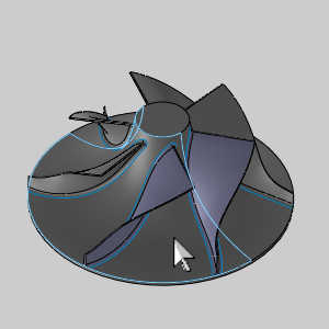
In this example, you create toolpaths that can be used to rough and finish the impeller.

Section 1) Roughing
Part 1) Add the Feature
-
 CAM Tree tab.
-
Right-click
 Machine
Setup and click Mill Multiaxis.
Machine
Setup and click Mill Multiaxis. -
In the Multiaxis Wizard, click Multiblade.
-
Click Next>> to go to the Posting dialog box.
Part 2) Define the Posting Parameters
-
The Work Offset # is automatically set to the value defined in the Machine Setup dialog box.
You can change the value here to update the Work Offset # for the feature. -
Click Next>> to go to the Multiaxis Posting dialog.
Part 3) Define the Multiaxis Posting Parameters
-
Notice, at the top of the dialog box, that the Use Machine Settings check box is selected.
This means that the Multiaxis Posting parameters for the feature use the same parameters as the machine that is selected in Current Settings.
You can clear the Use Machine Settings check box to define the Multiaxis Posting parameters of the feature separately from the current machine settings.
An example usage is explained later. -
Click Next>> to go to the Tool page.
Part 4) Select the Roughing Tool
-
Click the Tool Crib button.
The Tool Crib dialog appears. -
Select the Tapered tool type on the left of the dialog to show the tapered tools available in the Tool Crib.
-
Highlight the 0.250 Diameter Tapered and click OK.
The Tool Crib dialog disappears. -
Click Next>> to go to the Parameters.
Part 5) Surface paths
-
In the Depth step group, change the Maximum distance - Distance to 0.125.
-
In the Stepover group, change the Maximum distance to 0.125 as well.
The rest of the values will be left at their default values.
Part 6) Part definition
-
Click the Part definition tab.
-
Click the ellipses button next to Blades,splitter,fillets to select geometry for the feature.
The Re/Select Geometry dialog appears. -
Select each surface of the two differently colors blades.


Be sure to select the shroud surface shown in the image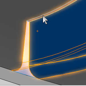
Selecting the surface in the image below is not necessary.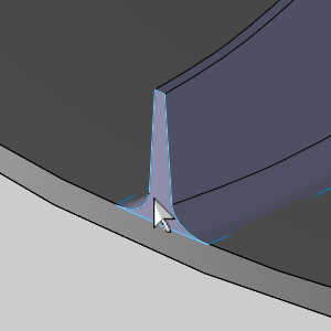
-
In the Feature Geometry Picking dialog, click OK.
The Mill Multiaxis Wizard returns. -
Click the ellipses button next to Hub.
The Re/Select Geometry dialog appears. -
Select the surface of the hub.

-
In the Feature Geometry Picking dialog, click OK.
The Mill Multiaxis Wizard returns. -
Next to each of the geometry selection buttons is a Stock to leave value. Set both of these to 0.030.
-
At the bottom of the Part definition group, set the Number of segments value to 6.
-
In the Segments group, set Machine to All.
Tip: While this tutorial will have you toolpath the entire part, a more common practice is to rough 3 pockets and finish the 2 blades the roughing exposes. This allows you to ensure there are no gouges and utilize macros on the machine to complete the rest of the part.
-
Click Compute.
Part 7) Simulation
For more help using simulation, view Getting Started with Simulation.
-
To view the program, in the Quick access menu of the CAM Tree, click
 Simulation.
 -
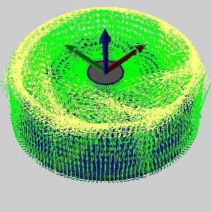
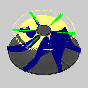
Click Play to view the Roughing operation in simulation.
This will allow you to ensure this operation is free of collisions.
In this case, we can see there is indeed an issue with the cut.
-
To close simulation, in the
 Exit Simulation.
Part 8) Adjust the Parameters and Compute
-
In the CAM Tree, right-click the Feature Multiaxis and select Edit.
The Mill Multiaxis Wizard appears. -
Click Parameters in the tree on the left.
-
In the Sorting group, change Method to Zig-zag, start from leading edge.
-
Click on the Tool axis control tab and change the Side tilt angle value in the Tilting group to 0.
-
Click on the Edges tab and change the Radial/Trailing edge value in the Edge extension group to 0.250.
-
Click Compute.

Part 9) Simulation
-
To view the program, in the Quick access menu of the CAM Tree,
Simulation. -
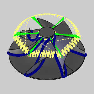
Click Play to view the Roughing operation in simulation.
We can see this has corrected the gouge issue.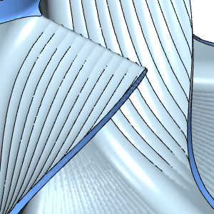
-
To close simulation, in the
Exit Simulation. -
In the CAM Tree, right-click the Feature Multiaxis feature, and select Blank/Unblank Toolpath.
-
You can also click the small arrow next to the feature to collapse it.
-
In the File menu, click Save.
Section 2) Hub Finishing
Part 1) Add another Feature
-
Right-click
Machine
Setup and click Mill Multiaxis. -
In the Multiaxis Wizard, select Multiblade.
-
Just as in the first feature, we will be leaving the Posting and Multiaxis Post pages as they are.
In the tree on the left of the wizard, click Rough to jump past the posting pages to the tool page.
Part 2) Select the Finishing Tool
-
Click the Tool Crib button.
The Tool Crib dialog appears. -
Select the Tapered tool type on the left of the dialog to show the taper tools available in the Tool Crib.
-
Highlight the 0.2500 Diameter taper and click OK.
The Tool Crib dialog disappears. -
Click Next>> to go to the Parameters.
Part 3) Surface paths
-
In the Pattern group, set Machining to Hub finishing.
-
In the Stepover group set the Maximum distance to 0.03.
Part 4) Part definition
-
Click the Part definition tab.
-
Click the ellipses button next to Blades,splitter,fillets to select geometry for the feature.
The Re/Select Geometry dialog appears. -
-
Click OK.
The Mill Multiaxis Wizard returns. -
Click the ellipses button next to Hub.
The Re/Select Geometry dialog appears. -
Select the surface of the hub.
-
Click OK.
The Mill Multiaxis Wizard returns. -
At the bottom of the Part definition group, set the Number of segments value to 6.
-
In the Segments group, set Machine to All.
-
Click Compute.
Part 5) Simulation
-
To view the program, in the Quick access menu of the CAM Tree, click
Simulation. -
Click Play to view the Finishing operation in simulation.
This will allow you to ensure this operation is free of collisions and to check the deviation report to verify removal of all the material. -
Once the simulation is finished click in the Analysis tab and choose Deviation from the drop down list.
-
Click
 Min/Max Detection, and then
  Refresh Cutsim to view the deviation report.
Notice the hub surface is right where we need it to be. -
To close simulation, in the
Exit Simulation. -
In the CAM Tree, right-click the Feature Multiaxis feature, and click Blank/Unblank Toolpath.
-
You can also click the small arrow next to the feature to collapse it.
-
In the File menu, click Save.
Section 3) Blade Finishing
Part 1) Add another feature
-
Right-click the last Multiaxis feature and select Copy with Geometry.
-
Right-click the same feature and select Paste.
A new feature is added to the tree.
Part 2) Edit the feature
-
Right-click this new feature and select Edit.
-
Select Parameters from the tree on the left.
-
In the Pattern group, set the Machining option to Blade finishing.
-
In the Depth step group, set the Distance to 0.03.
-
Click the Part definition tab.
-
Click the ellipses button next to Blades,splitter,fillets to select geometry for the feature.
The Re/Select Geometry dialog appears. -
Deselect the surfaces on one of the blades and its fillets.
-
Click OK.
-
Click Compute.
Part 3) Simulation
-
To view the program, in the Quick access menu of the CAM Tree, click
Simulation. -
Click Play to view the Finishing operation in simulation.
This will allow you to ensure this operation is free of collisions and to check the deviation report to verify removal of all the material. -
Once the simulation is finished click in the Analysis tab and choose Deviation from the drop down list.
-
Click
Refresh Cutsim to view the deviation report.
Notice the blade surfaces are right where we need it to be. -
To close simulation, in the
Exit Simulation. -
In the CAM Tree, right-click the Feature Multiaxis feature, and click Blank/Unblank Toolpath.
-
You can also click the small arrow next to the feature to collapse it.
-
In the File menu, click Save.
Section 4) Fillet Finishing
Part 1) Copy and Paste the feature
-
Right-click the last Multiaxis feature and select Copy with Geometry.
-
Right-click the same feature and select Paste.
A new feature is added to the tree.
Part 2) Edit the tool
-
Right-click this new feature and select Edit.
-
In the tree on the left of the wizard, click Taper Mill to jump past the posting pages to the tool page.
-
Click the Tool Crib button.
The Tool Crib dialog appears. -
Select the Tapered tool type on the left of the dialog to show the taper tools available in the Tool Crib.
-
Highlight the 0.1250 Diameter taper and click OK.
The Tool Crib dialog disappears.
Part 3) Update the Surface paths options
-
Click Next>> to go to the Parameters.
-
Select Parameters from the tree on the left.
-
In the Pattern group, set the Machining option to Fillet finishing.
-
In the Both sides group set the:
-
Number of cuts to 3.
-
Distance to 0.010.
-
-
Click Compute.
Part 4) Simulation
-
To view the program, in the Quick access menu of the CAM Tree, click
Simulation. -
Click Play to view the Finishing operation in simulation.
This will allow you to ensure this operation is free of collisions and to check the deviation report to verify removal of all the material. -
Once the simulation is finished click in the Analysis tab and choose Deviation from the drop down list.
-
Click
Refresh Cutsim to view the deviation report.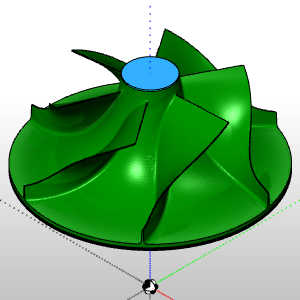
Notice the blade surfaces are right where we need it to be. -
To close simulation, in the
Exit Simulation. -
In the CAM Tree, right-click the Feature Multiaxis feature, and click Blank/Unblank Toolpath.
-
You can also click the small arrow next to the feature to collapse it.
-
In the File menu, click Save.
This concludes the tutorial.