Turn Mill Example
Introduction
This tutorial explains how to create a Turn Mill operation and adjust some of the most commonly used settings.
Example File
The part file for this tutorial is available for download at: http://www.bobcad.com/helpfiles. If you are connected to the Internet, you can click the link provided to download and save the Turn Mill Example 1.SLDPRT zip file. After extracting the zip file, you can then open the example file to use with this tutorial. In the example file provided, the Tool Crib is already equipped with the necessary tools and the stock and Machine Setup are already defined. The part is simulated using the BC_Porting_4x_HeadTable_Rotary_Only machine.

Part 1) Add the Feature
-
 CAM Tree tab.
-
Right-click
 Machine
Setup and click Mill Multiaxis.
Machine
Setup and click Mill Multiaxis. -
In the Multiaxis Wizard, click Turn Milling.
-
Click Next>> to go to the Posting dialog box.
Part 2) Define the Posting Parameters
-
The Work Offset # is automatically set to the value defined in the Machine Setup dialog box.
You can change the value here to update the Work Offset # for the feature. -
Click Next>> to go to the Multiaxis Posting dialog box.
Part 3) Define the Multiaxis Posting Parameters
-
Notice, at the top of the dialog box, that the Use Machine Settings check box is selected.
This means that the Multiaxis Posting parameters for the feature use the same parameters as the machine that is selected in Current Settings.
You can clear the Use Machine Settings check box to define the Multiaxis Posting parameters of the feature separately from the current machine settings.
For this example, no changes are needed (more information is provided later). -
Click Next>> to go to the Tool page.
Part 4) Define the Tool Parameters
-
In the Tool page, click Tool Crib.
The Tool Crib dialog appears. -
Select the Rough+2 tool and click OK.
The Tool Crib disappears and the Rough+2 tool is now assigned. -
Click Next>> to go to the Parameters.
Part 5) Surface paths
-
In the Sorting group, set the Axial moves to Uni-directional / Positive.
This sets tool to cut in a single direction along the axis, and forces it into a positive direction.
-
In the Depths steps group set the Distance to 0.125.
-
In the Stepover group set the Max. stepover to 0.250.
Part 6) Part definition
-
Click on the Part definition tab to jump to define the geometry.
-
Next to Part, click the drop down on Turn profile and set it to Part surface.
This will allow us to select the solid as geometry rather than using a wireframe profile. -
Click the ellipses button next to Part surface.
The Mill Multiaxis wizard disappears and the -
Select the check box for Select whole bodies.
-
Select the model.

-
Click OK.
The Mill Multiaxis Wizard returns. -
Set the Stock to leave value to 0.05.
-
Click the Axis of rotation button.
The Rotation axis dialog appears. -
By default the By base point and direction option is selected.
Set the Direction to X, and click OK.
The dialog disappears. -
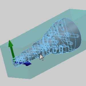
Click Compute.

Notice we are machining all the way to the back of the stock.
We will update this in the next part.
Part 7) Edit the Machining area
-
Right click the feature in the CAM Tree and select Edit.
-
Click Parameters in the tree on the left of the wizard.
-
Click the Part definition tab.
-
In the Part definition group click the Machining area button.
The Machining area dialog appears. -
In the User limits group select the check box for Axial.
-
Set the End value to 6.750.
-
Click OK.
The dialog disappears. -
Click Compute.

Part 8) Simulation
For more help using simulation, view Getting Started with Simulation.
-
To view the program, in the Quick access menu of the CAM Tree, click
 Simulation.
 -
Click Play to view the current operation.

-
Set the Stock to Transparent and the Workpiece to Show.

Notice we are machining to the end of the part but do not collide with the chuck.
This was adjusted by limiting our machining area. -
To close simulation, in the
 Exit Simulation.
Part 9) Edit the feature
In this part of the example we will adjust the axis offset, and the link type to see how they affect the resulting toolpath.
-
Right-click the feature and select Edit.
-
Click Parameters.
-
In the Axis offset group, set the Tool diameter (%) to 10.
This will move the tool closer inline with the axis of rotation.
| Tool diameter (%) : 40 | Tool diameter (%) : 10 |

|

|
-
In the Non-cutting moves group, update the Ramp angle to 20.
This adjusts the angle of the entry move.
| Ramp angle : 5 | Ramp angle : 20 |

|

|
-
Click Compute.
This concludes the example.