Post Processor Lessons - Lesson 12
POST MODIFICATION LESSON 12: 5 AXIS OUTPUT
In this lesson we are going to cover the different methods of output for 5 axis motion.
We will cover:
- No Machine Compensation
- Machine Compensation in Z Only
- Machine Hybrid Compensation (Mixed Mode)
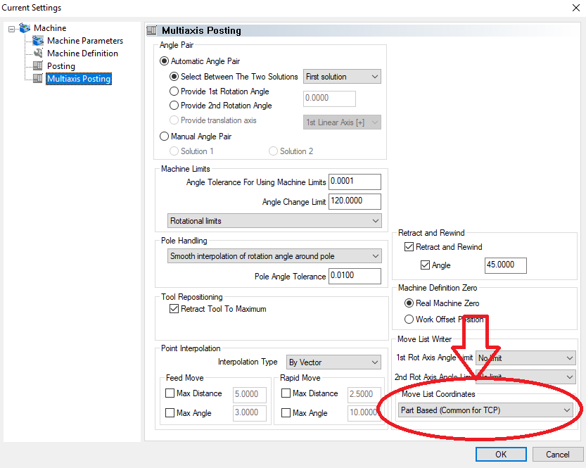
- Part Based (Common for TCP)
We are going to use the following files for this lesson:
|
|
|
Special Note about Multiaxis Post Processors
When working on multiaxis post processors it is very important that the Machine Definition files are correctly configured and used. The posting engine uses the kinematics defined in the Machine Definition to calculate the position moves for the NC program. The output described in this lesson is set on the Multiaxis Posting Page under the CAM Defaults>Current Settings>Multiaxis Posting page as shown in the following image. Additional Machine Definition settings that affect output will also be reference throughout this lesson.
No Machine Compensation (Not very common)
With this mode active the system compensates for any rotations of the tool/part so that the tip of the tool is in the correct location on the part to cut correctly. The software is doing all the calculations based on the rotation of the part/tool and adjusts the NC coordinate as necessary.
To see an example you can Open the file Post Guide – Lesson 12-1.bbcd This file uses the machine BC_Head_Head that is installed with the software. This is a 5 axis machine where the 4th and 5th axes of the machine are rotaries that are on the head of the machine.
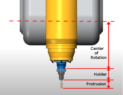
When working with a machine that has no compensation method for the length of the tool the BobCAD-CAM posting engine compensates using the following values:
- Center Point Definition (XYZ) in the Machine Definition
- Holder Length
- Tool Protrusion Length
Machine Compensation in Z Only (Very common)
This common output method is used for machines where the standard G43 type offsets are used but the machine does not TCP/RTCP to track and compensate for tool length on 5 axis moves.
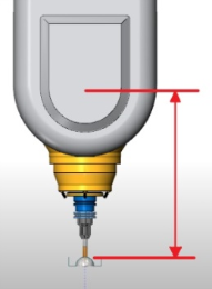
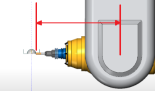
With this mode the initial vertical tool orientation is compensated for with normal offsets, and as the tool is rotated off of vertical down to horizontal the coordinates need shifted. The more the tool is rotated off of vertical the more the coordinates need to be shifted until the tool reaches horizontal where the entire gauge length will then be applied.
|
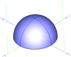
In this image the Z axis position would be Z1.0 as the radius of the spherical part is 1.00 with Z0.0 in the center of the sphere. |
|
|
In this image the Z axis position would be Z- gauge length, and the X axis would be shifted by the gauge length + the radius of the sphere. |
|
With this mode when the posting engine encounters the “length_offset” command variable the posting engine then calls Post Block: 14 for standard G43 tool length offsets to be output into the NC program.
Machine Hybrid Compensation (Mixed Mode)
Some machines have the ability to compensate for the length of the tool and holder from the spindle face but do not compensate for the pivot length of the machine. In the BobCAD-CAM posting engine we refer to this as Hybrid Compensation. When this mode is used the coordinates are shifted for the Center Point distances defined in the Machine Definition but the controller on the machine tool handles the compensation for the length of the Tool and Holder. (Thermwood 9100 CNC Controllers use this mode for an example)
Part Based (Common for TCP)
For machine controllers that are able to compensate for the length of the tool and the pivot length this mode is used. When this mode is used the coordinates are output on the part itself and no shifting is done by the posting engine.
With this mode when the posting engine encounters the “length_offset” command variable the posting engine then calls Post Block: 45. which is used for 5 axis tool length offsets to be output into the NC program.


