Post Processor Lessons - Lesson 9
POST MODIFICATION LESSON 9: ROTARY AXIS INTRODUCTION
In this lesson we are going to go over how the rotary output is handled in posting.
We will cover:
- Rotary variables and how they are used
- Rotary Prefix for Variables
- Rotary Axis Position Output Modes
We are going to use the following files for this lesson:
|
|
|
We will get started with the explanation of the rotary variables and their prefix. Then examples to show use.
Rotary Variables and How They Are Used
In the post processor there are different variables for different types of rotary motion. Indexing uses a set of variables for output vs. simultaneous motion which uses a different set of variables.
Indexing uses the following variables:
Simultaneous motion uses the following variables:
For indexing you will notice the variables are not used in the toolchange Post Blocks themselves .Looking at Post Block 2. you will see command variables:
These command variables are directing the posting engine to call alternate Post Blocks to be processed for output. The “output_primary_rotary_index” command variable is directing the posting engine to call Post Block 10. Looking at Post Block 10. you will see an entire Post Line is defined for output.
n,primary_rotary_angle_output
Additionally the secondary and tertiary blocks are output from Post Blocks: 17 and 18.
Indexing where Direction Codes are required
The BobCAD-CAM posting engine supports the output of direction codes to tell the machine which direction to rotate the axis when indexing. This is used when Post Question 441. is set to a value of 1. Output of the direction codes are handled using the following variables:
The string values that will be output are defined on Post Questions: 710.-713. as shown below:
710. Primary Rotary CW direction code? "M13"
711. Primary Rotary CCW direction code? "M14"
712. Secondary rotary CW direction code? "M113"
713. Secondary rotary CCW direction code? "M114"
Looking at the following NC code you can see the rotary position move and the noted direction codes.
|
%
|
(NEXT CUT - SAME TOOL)
|
NOTE: The code has been abbreviated. Notice the last operation the direction code has not been output again with the rotary axis position code. This is because the posting engine uses Modality to determine if the code should be output again or not.
Rotary Prefix for Variables
The prefix used for the rotary position output variables are found on the following Post Questions:
722. Primary Rotary prefix string? "A"
723. Secondary Rotary prefix string? "B"
724. Third Rotary prefix string? "C"
NOTE: The Post Questions shown above control the prefix for all the rotary position output variables used for Indexing, Wrapping, and Simultaneous 4 axis cutting.
Rotary Axis Position Output Modes
When a machine has a rotary axis or axes mounted it is very important to understand the way the controller is configured to program the positions of the rotary axis. Because of this the BobCAD-CAM posting engine supports multiple Rotary Axis Position Output Modes. These modes are defined on Post Question: 440.
440. What is the rotary output type (0=Abs Pos 1=Signed ABS 2=Signed Continuous) ? 0
There are 3 different output modes supported. Each mode is defined below:
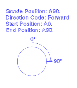
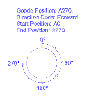
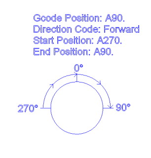
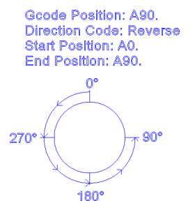
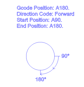
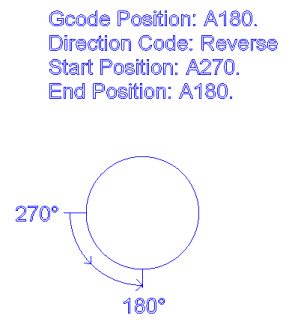
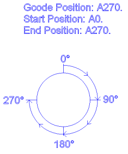
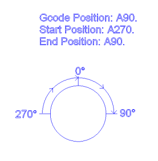
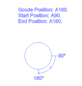
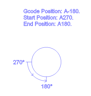
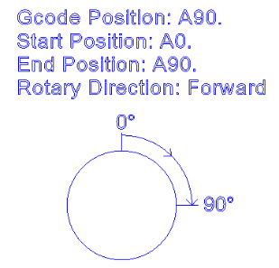
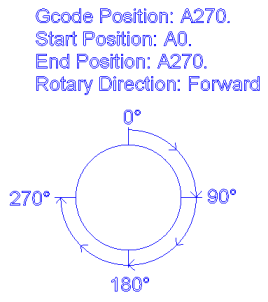
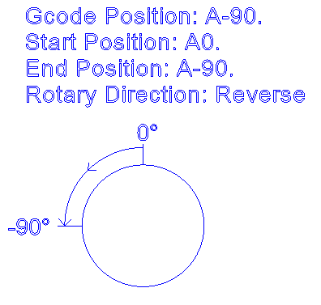
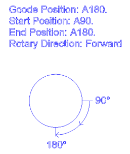
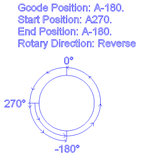
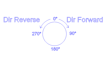
0 – Absolute Position Mode – In this mode the rotary locations are defined as an absolute position and do not change. The direction is defined by a separate G or M code in the NC file. Using this mode tells the posting engine to output the indexing direction string values that are defined on Post Questions:710. thru 713. Examples of different positioning using this output mode are shown below.
|
|
|
|
|
|
|
|
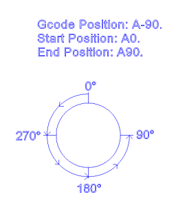
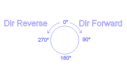
1 – Absolute Position Signed Direction – In this mode the rotary locations are defined as an absolute position and do not change. The direction is defined by positive or negative rotary position values in the NC file. Using this mode tells the posting engine to output the indexing positions using the positive or negative values to define the direction the machine to move the rotary axis. Examples of different positioning using this output mode are shown below.
|
|
|
|
|
|
|
|
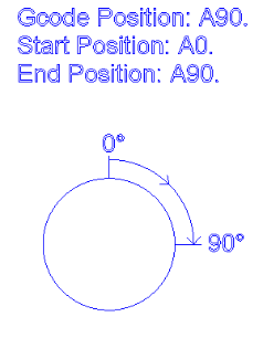
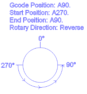
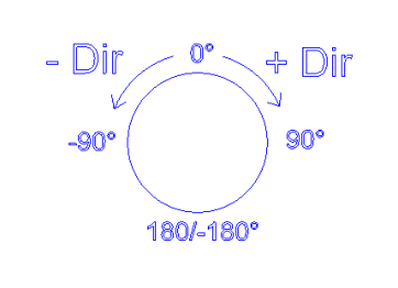
2 – Signed Continuous – In this mode the rotary locations are defined in a positive or negative position. The positions are best understood if you think of a number line where you have positive values going to the right and negative positions to the left with Zero in the center. Wrap up that number line into a circle and you have the positions for the rotary axis.

As shown on the number line above the position of A90. and A-90. are NOT the same location. The direction is defined by the location of the new position relative to the current position in the NC file.
|
|
|
|
|
|
|
|
Lesson 9 – Step 1:
Open the BC_4x_Mill.BCPst file in your editor. Also open the Post Guide – Lesson 9.bbcd file inside the BobCAD-CAM software.
There are two features already created on this part file. The first feature is an Index System that will be generating a 4 axis Indexing output. The second is a 4 Axis Rotary toolpath that will create 4 Axis Simultaneous output from the post processor. These two features will show us how the output of each variable set is used.
Lesson 9 – Step 2
Generate the NC code and open the code in your editor next to your post processor so you can look at both files at the same time as shown below. Working this way makes it easier when making modifications to post processor files.
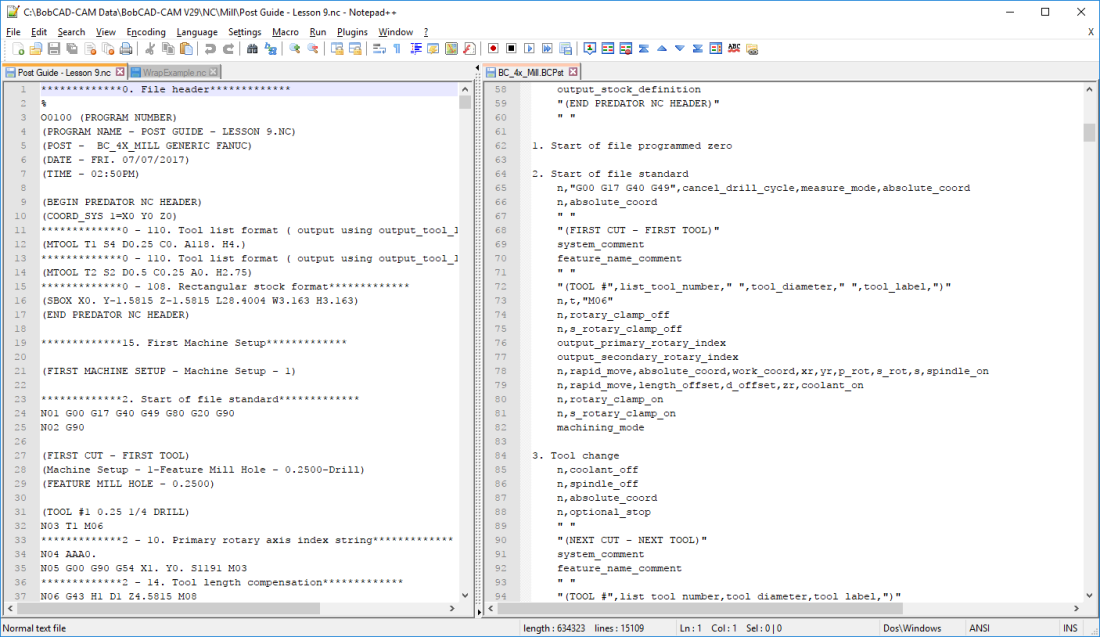
Notice in the NC output file that the debugging parameters are turned ON and on line “N04” we have the Angle output value with the prefix “A”.
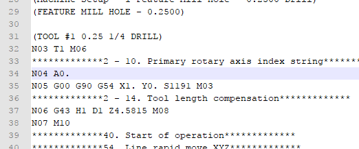
Looking at the Debug line above the rotary position output we can see that Post Block: 2. and Post Block 10. are the ones outputting the code. We will start by looking at Post Block: 2.
In the post processor at Post Block: 2. we can see the following command variables:
Theoutput_primary_rotary_index command variable is telling the posting engine to call Post Block: 10. process the block and then return to this location and continue processing the rest of Post Block: 2. The same happens when the posting engine reads the output_secondary_rotary_indexcommand variable.
In the post processor, navigate to Post Block: 10. and notice the output Post Line of this block.
10. Primary rotary axis index string
n,primary_rotary_direction,primary_rotary_angle_output
Notice that there is the line number output, the rotary direction output variable, and finally the rotary position output itself. If you need to make modifications to the indexing output, this Post Line is where the modifications would take place. Note that the same applies for secondary rotary axes if you are working with a 5 axis machine using indexing motion.
To change the prefix that is output with the rotary axis position in the NC output code reference Post Lines: 722. thru 724.


