Post Processor Lessons - Lesson 10
POST MODIFICATION LESSON 10: ROTARY AXIS CONTINUED
In this lesson we are going to continue with additional Rotary Axis output.
We will cover:
- Wrapping Configuration in the Post Processor
- Inverse Time Feedrates
We are going to use the following files for this lesson:
|
Machine File: BC_4x_Mill
|
|
Wrapping Configuration in the Post Processor
When you are configuring a post processor that will be used on a 4 or 5 axis machine, where Wrapping Groups will be used, you must configure 3 Post Questions in the Post Processor for the correct output to be achieved.
The 3 Post Questions shown below define which axis on the machine is the 1st, 2nd, and 3rd rotation axes on the machine.
442. Wrapping X axis is (1=primary 2=secondary 3=tertiary)? 1
443. Wrapping Y axis is (1=primary 2=secondary 3=tertiary)? 2
444. Wrapping Z axis is (1=primary 2=secondary 3=tertiary)? 3
Looking at the 3 Post Questions above, notice line 442. is set to a value of 1. This is defining the X axis as the primary axis of rotation. This shows the correct configuration for a 4 axis milling machine where the rotary axis is setup to rotate around the X axis of the machine.
442. Wrapping X axis is (1=primary 2=secondary 3=tertiary)? 2
443. Wrapping Y axis is (1=primary 2=secondary 3=tertiary)? 1
444. Wrapping Z axis is (1=primary 2=secondary 3=tertiary)? 3
Looking at the 3 Post Questions above, notice line 443. is set to a value of 1. This is defining the Y axis as the primary axis of rotation. This shows the correct configuration for a 4 axis milling machine where the rotary axis is setup to rotate around the Y axis of the machine.
NOTE: When you need to reverse the direction of only the wrapping rotation output simply change the value of the setting on these Post Questions to a negative of the setting for the axis you wish to reverse. Example shown below demonstrates how to set primary rotation around the X axis but reverse the wrapping direction output.
442. Wrapping X axis is (1=primary 2=secondary 3=tertiary)? -1
443. Wrapping Y axis is (1=primary 2=secondary 3=tertiary)? 2
444. Wrapping Z axis is (1=primary 2=secondary 3=tertiary)? 3
Inverse Time Feedrates
Inverse time feedrates are commonly used when cutting with single or multiple rotary axes on a machine tool where rotation moves are included during cutting motion. The BobCAD-CAM posting engine controls the mode the feedrates should be output by Post Question: 441.
441. Multiaxis feed type (0=UPM 1=INV on all 2=INV on Rotary 3=INV on 4 and 5 Axis) ? 2
The mode the feedrates should be output are handled by the posting engine based on the type of cutting and the appropriate feed mode based on the setting of Post Question 441. The variables used and affected by Post Question 441.:
Definitions of Post Question: 441
0 – UPM – This setting will set the posting engine to output the feed motion in the NC program as it normally would for 3 axis type cutting. This mode is in UPM which stands for Units Per Minute. The units could be in Inch or Metric depending on the file and post processor configuration.
1 – Inverse on all – This setting will force all feedrate motion in the NC file to be output in Inverse Time feedrate mode. Normally you would only run motion where rotation is happening during a cutting move but it is possible on some machine tools to use Inverse Time feedrates on motion where only XYZ motion exists. This setting will make all motion output in Inverse Time regardless if there is any rotary motion or not.
2 – Inverse on Rotary – This setting is the commonly used option for most controllers that support Inverse Time feedrates. Using this option will make the posting engine switch between UMP and Inverse Time feedrates on each line based on if Rotary Motion is output on the line.
3 – Inverse on 4 and 5 Axis – This setting is used when you only wish inverse time feedrates to be output when 4 and 5 axis feature types are programmed in the software.
Lesson 10 – Step 1:
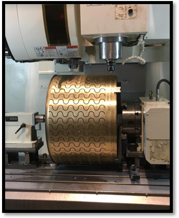
In this step we will look at the wrapping configuration. If the machine we are working with has the rotation axis mounted to the table so that the rotary axis is rotating around the machine’s X axis as shown in the picture below then we need to make sure the wrapping Post Questions are properly configured.

In the post processor, navigate to the Post Question: 442.
442. Wrapping X axis is (1=primary 2=secondary 3=tertiary)? 1
443. Wrapping Y axis is (1=primary 2=secondary 3=tertiary)? 2
444. Wrapping Z axis is (1=primary 2=secondary 3=tertiary)? 3
To have the correct wrapping direction for a machine shown above where the rotary axis is aligned and rotating around the X axis we need to make sure the Wrapping X axis is set to a value of “1”. If the rotary output is found to be going in the wrong direction with this setting then simply change the value to “-1” to reverse the wrapping direction.
Post and open the NC code in your editor. Notice the “A” axis rotary position output moves that are written into the NC file.
Now change the setting of Post Question: 442. to a value of “-1”, Save the post processor and output and edit the NC code again. Notice this time the position moves for the rotary “A” axis have changed.
Lesson 10 – Step 2:
In this step we will be looking at the Inverse Time feedrate output. With the post processor opened in your editor navigate to the Post Question: 441. The default setting for this Post Question should be "2" in the BC_4x_Mill.BCPst file. If your is not set to a value of 2, please change it to a value of “2” now and save the post processor.
Generate the NC output file and open in your editor with the post processor. Notice how the motion with the rotary now has a Gcode “G93” and a feedrate on almost every line of code. Please read the following note to understand a little more about Inverse Time feedrates.
Inverse Time Feedrate – What is it?
Inverse Time feedrates are a way of output to the cnc machine’s controller how fast the axes on the machine tool should move to achieve the motion at the correct speed. What happens is the distance traveled by the tool on the part for each axis is calculated and based on the programmed feedrate, the time it should take for the machine to execute the required motion is calculated. Then the inverse of that time value is output as a feedrate value into the NC code.
The reason for this type of calculated feedrate is to solve the problem encountered by UPM (unit per minute) feeds for machines where multiple rotary axes exist on a machine. When you are using UPM feedrates there is no way for the controller to know which rotary axis needs to move at the programmed feed. For a rotation of 15 degrees on the 1st rotary axis and 50 degrees on the secondary rotary axes, each rotary must move at different speeds to arrive at their destination at the same time. With inverse time feedrates the controller can take the time interval and move each of the machines axes at the required speed so they arrive at their programmed position in the defined amount of time.
The reason for a feedrate command on every line of code is due to the fact that the feedrate value must be calculated for each move of the program. On Fanuc based controllers the gcode that commonly represents Inverse Time feedrates is “G93”.


