The Rotate function rotates geometry around a defined axis, with optional copying and/or scaling, using Dynamic Drawing. Dynamic Drawing allows you to use data entry or sketch handles to define the rotation angles and rotation origin. The benefit of Dynamic Drawing is that both methods can be utilized at any time during creation. You can use the sketch handles to get close to the desired result and then update the Data Entry parameters to get the exact value.
Rotate supports the use of the snap increment when using the sketch handles to set the rotation angles or rotation origin location. The snap increment allows you to get precise results when using mouse selection and helps to reduce data entry modifications.
To learn more, view Snap Increment.
To open Rotate, do one of the following:
The parameters display in the ![]() Data Entry tab of the Data-CAM Tree Manager.
Data Entry tab of the Data-CAM Tree Manager.
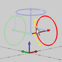
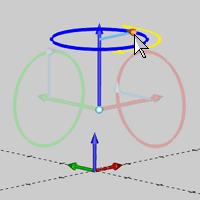
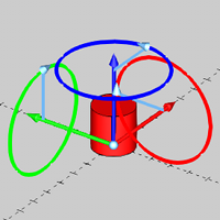
The Angle Around Axis parameters allow you to define the amount of rotation around each of the three coordinate axes: X, Y, and Z. Dynamic Drawing allows you to modify these parameters using data entry, sketch handles, or a combination of both. When using sketch handles, the snap increment applies.
TIP: The Rotation Angle sketch handles points in the positive direction of rotation based on the right-hand rule.
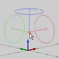
The origin parameters define the center of rotation for the selected geometry. You can use the origin handle to set the origin by selecting the snap point of another entity or any arbitrary location in the workspace, or you can type values in the Data Entry Manager to define the origin location. Dynamic Drawing provides the ability to do both. When using the origin handle, the snap increment applies.
X - determines the X-axis location of the rotation origin in reference to the active UCS.
Y - determines the Y-axis location of the rotation origin in reference to the active UCS.
Z - determines the Z-axis location of the rotation origin in reference to the active UCS.
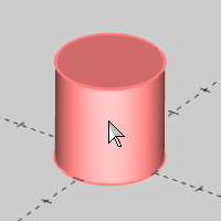
1 Open the function and select the geometry to rotate.
This can be wireframe, solids or both.
TIP: When rotating solids, a Rotate feature is added to the CAD Tree.
(You can also define all Data Entry parameters before selecting geometry, but it is often beneficial to select the geometry first and create the CAD preview so you can visualize the changes made to the Data Entry parameters.)
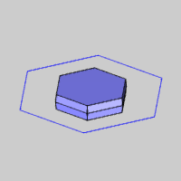
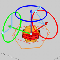
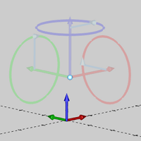
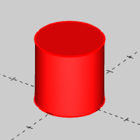
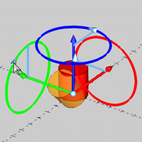
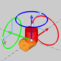
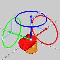
2 Confirm (OK) the selection to create the CAD preview and display the rotation sketch handles (this includes the rotation origin, and rotation angle for each axis).
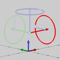
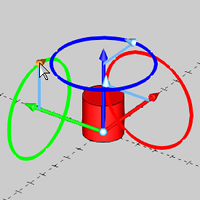
3 Use sketch handles or data entry to modify the rotation angles and rotation origin as needed.
You can modify the snap increment value or turn it off if you are using sketch handles.
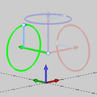
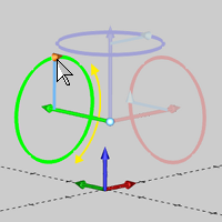
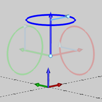
In the following images, the Y-axis rotation angle is modified using sketch handles before typing the final value in the Data Entry Manager.
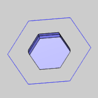
4 Click OK to rotate the geometry as shown in the CAD preview. (The geometry is rotated and the CAD preview updates to the new position.)
5 To rotate other geometry, click Re/Select and repeat the process.
6 Click Cancel to close the Data Entry Manager.
For each solid entity that you rotate, a feature is added to the CAD Tree that retains your results. This allows for editing, suppressing, and more as explained in The CAD Tree.