Translate (Move) Translate (Move)
In this Topic Show
The Translate function is used to move geometry, with optional copying and scaling, using Dynamic Drawing. Dynamic Drawing allows you to use data entry or sketch handles to define the distance and direction that the geometry moves. The benefit of Dynamic Drawing is that both methods can be utilized at any time during creation. You can use the sketch handles to get close to the desired result and then update the Data Entry parameters to get the exact value.
Translate supports the use of the snap increment when using the sketch handles to set the distance values or origin location. The snap increment allows you to get precise results when using mouse selection and helps to reduce data entry modifications.
To learn more, view Snap Increment.

To open Translate, do one of the following:
icon.
The parameters display in the  Data Entry tab of the Data-CAM Tree Manager.
There are two methods to use when translating geometry: Sketch/Enter or Drag. The Data Entry parameters are explained next with the options that are available for each method.
NOTE: With the addition of Dynamic Drawing, the Drag method now supports both of the previous methods: Drag and Delta. You simply enter values in the XYZ boxes of the End group to define an incremental distance from the current location (delta).
The Sketch/Enter method allows you to translate (move) geometry by specifying the start point and end point of the move. The start and end can both be defined using either data entry or sketching (clicking a snap point or anywhere in the Workspace). The geometry is then translated the same distance and direction as defined by the reference points.
TIP: The start point and end point, or reference points, for the Sketch/Enter method can be on the geometry or anywhere in the Workspace. Note that you can also define the start and end using a combination of Pick and Enter.
Start
You can define the start point (called the move from location) using the Pick option, to select the start point using the mouse, or you can use the Enter option and type the coordinates in the Data Entry Manager as follows.
X - determines the X-axis location of the start point of the translation move in reference to the Active UCS.
Y - determines the Y-axis location of the start point of the translation move in reference to the Active UCS.
Z - determines the Z-axis location of the start point of the translation move in reference to the Active UCS.
End
You can define the end point (called the move to location) using the Pick option, to select the end point using the mouse, or you can use the Enter option and type the coordinates in the Data Entry Manager as follows.
X - determines the X-axis location of the end point of the translation move in reference to the Active UCS.
Y - determines the Y-axis location of the end point of the translation move in reference to the Active UCS.
Z - determines the Z-axis location of the end point of the translation move in reference to the Active UCS.
The Drag method allows you to use dynamic sketch handles to determine the distance and direction that the geometry moves. You can use the origin sketch handle to move the geometry to any location that you click in the Workspace or to the snap points of other entities. This location can then be modified using data entry. You can also use the linear sketch handles to move the geometry along any one of the three coordinate axes: X, Y, or Z. As with the origin handle, you can use the linear sketch handles to get close to the final result and then use data entry to update to exact values.
When using sketch handles to modify the translation parameters, the snap increment applies.
End
The End group in the Data Entry Manager displays the coordinates for the translation move from the current geometry location. When you select geometry, the translation origin is placed at the center of the geometry and this becomes the X0 Y0 Z0 location for the End group. You can then type values to determine the change in location from the current origin, or you can use sketch handles to modify the origin.
X - determines the change in distance along the X-axis from the current geometry origin.
Y - determines the change in distance along the Y-axis from the current geometry origin.
Z - determines the change in distance along the Z-axis from the current geometry origin.
The following Data Entry parameters are available for both translation methods: Drag and Sketch/Enter.
Scale Off |
Scale On |
Click |
Drag |
|
|
|
|
 From Center
- With this check box cleared,
the selected geometry will scale from the WCS. This means that its
position in the graphics area is scaled as well.
From Center
- With this check box cleared,
the selected geometry will scale from the WCS. This means that its
position in the graphics area is scaled as well.
 From Center - With
this check box selected, the selected geometry will scale from its
bounding center. This means that its position in the graphics area
will no be affected.
From Center - With
this check box selected, the selected geometry will scale from its
bounding center. This means that its position in the graphics area
will no be affected.
Click here to see
an example.
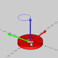
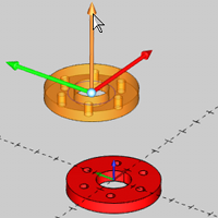
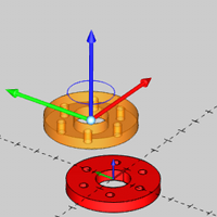
In the following example, translate is used to align a flange with a circle using both sketch handles and data entry.
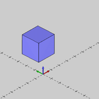
1 Open the function, click Drag in the Data Entry Manager, and select the geometry to translate.
This can be wireframe, solids or both.
TIP: When translating solids, a Translate feature is added to the CAD Tree.
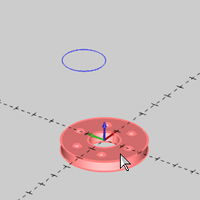
(You can also define all Data Entry parameters before selecting geometry, but it is often beneficial to select the geometry first and create the CAD preview so you can visualize the changes made to the Data Entry parameters.)
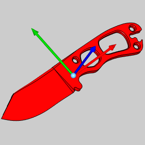
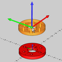
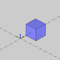
2 Confirm (OK) the selection to create the CAD preview and display the translation sketch handles (this includes the translation origin, and linear handles for each axis).
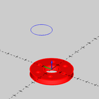
3 Use sketch handles or data entry to translate the geometry as needed.
You can modify the snap increment value or turn it off if you are using sketch handles.
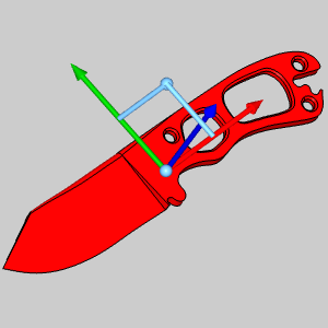
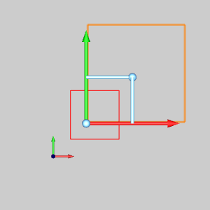
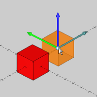
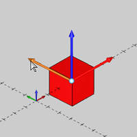
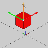
In the following images, the geometry is translated using the origin handle to place it at the snap point of a circle.
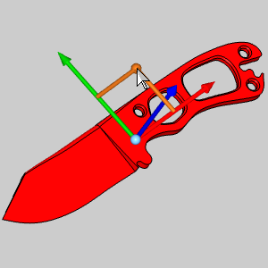
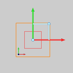
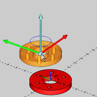
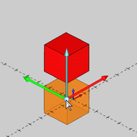
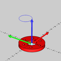
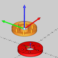
Next, the geometry is translated along the Z-axis using the sketch handle.
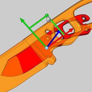
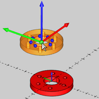
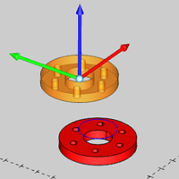
Now the final location is set by updating the Z value in the Data Entry Manager.
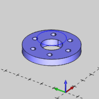
4 Click OK to translate the geometry as shown in the CAD preview. (The geometry is translated and the CAD preview updates to the new position.)
5 To translate other geometry, click Re/Select and repeat the process from Step 2.
6 Click Cancel to close the Data Entry Manager.
The general process for the Sketch/Enter method is as follows:
1 Select the geometry and confirm (OK) the selection.
2 Select or enter the Start point (move from location).
3 Select or enter the End point (move to location).
The options that you use determine how to perform the function.
IMPORTANT: If using Enter for both Start and End, you click OK to translate the geometry. If using Pick for either or both Start or End, the geometry is automatically translated when you click the respective point or points. Read the instruction in the Status Bar at the bottom of the user interface to help guide you through the function.
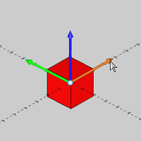
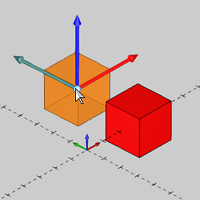
In the following example, translate is used to move a cube by the distance between its lower and upper corners using the Pick option for both the Start and End of the translation.
1 Open the function, and click Sketch/Enter in the Data Entry Manager.
2 Under Start, click Pick.
3 Under End, click Pick.
4 Select the geometry to translate and confirm (OK) the selection.
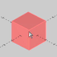
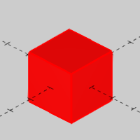

5 Click the Start point or move from location.
For the move from location, we hold Shift and click the cube to display its snap points before selecting the snap point at the lower corner.
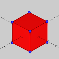
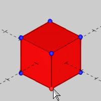

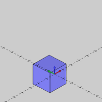
6 Click the End point or move to location.
For the end point, we click near the upper corner of the cube to select the closest snap point.
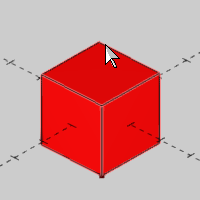
The geometry is translated when the move to location is selected.
For each solid entity that you translate, a feature is added to the CAD Tree that retains your results. This allows for editing, suppressing, and more as explained in The CAD Tree.