The window on the upper-right side of the tool crib provides a dynamic preview to help you visualize your tool and adapter mounting for Mill Turn jobs. The preview window displays the following items: the machine's tool devices (turrets or milling spindles), mounted adapters and/or tools, as well as a few coordinate system gnomons to help guide you when altering the mounting orientation of adapters.
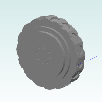
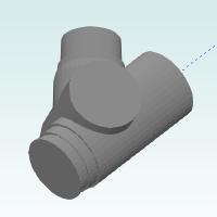
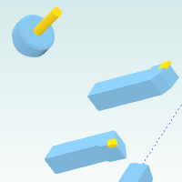
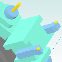
The preview window displays the tool devices for the current machine. These may be turrets or milling spindles as shown in the following images. Notice the dashed blue line. This indicates the Z-axis of the machine, or the lathe spindle's rotation axis, to help you visualize the orientation of the devices on the machine. (Note that the position of the devices in reference to the machine's rotation axis is exactly as defined in the machine definition. The face of the turret station or milling spindle geometry is aligned to X0 Y0 Z0, the virtual machine zero.)
The preview window displays any adapters that you mount to a tool device for the purpose of mounting lathe or milling tools. Note that when you select an adapter in the device tree, the adapter becomes highlighted and its mounting coordinate system displays as well as all coordinate systems that are defined for the turret station to which the adapter is mounted (An example is shown in the Gnomons section later in this document.) It is important to properly orient the adapters and to properly align them to the mounting location of the turret stations.
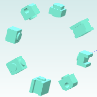
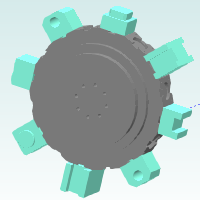
The tools that you mount to a tool device display in the preview window with their current mounting orientation as it is extremely important to properly mount and orient all tools before simulating or posting a program. Note that for turrets, all adapters and tools always display (unless you hide them). For milling spindles however, because there is only one mounting location, only the adapters and/or tools that you select in the device tree display in the preview window to make it clear which tool or adapter you are modifying.
There are a few coordinate systems that display in the preview window to help guide you when modifying the mounting parameters for tools and/or adapters. The following image shows three gnomons: the dynamic gnomon, the adapter mounting gnomon, and the turret station mounting gnomon. The preview window only displays the necessary gnomons based on what you are modifying (currently selected in the device tree).
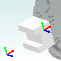
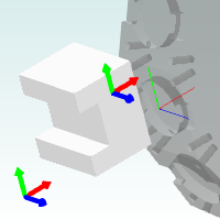
It is very helpful to understand how the gnomon in the lower-left corner of the preview window updates based on your selection in the device tree. This gnomon updates to indicate the parent coordinate system of the component selected in the device tree as follows:
Component Selected in Device Tree |
Dynamic Gnomon Updates to Show |
Device or Station |
Machine CS (From Machine Definition) |
Tool or Adapter Mounted to Station |
Station Mounting Location CS |
Tool Mounted to Adapter |
Adapter TMP (Tool Mounting Point) CS |
TIP: You can use the dynamic gnomon as your reference when modifying the mounting parameters of tools or adapters in the tool crib. (The adapter alignment, shift, and rotation parameters are in reference to axes directions shown by the dynamic gnomon.)
The thicker gnomon shown at the back of the adapter is the adapters mounting coordinate system, which is used to align the adapter to a device station. This is exactly as defined for the adapter in the Adapter Library and when properly defined, does not need to be altered. You can however use the mounting parameters to modify the adapter's orientation in reference to the device station's coordinate system.
The thin-lined gnomon displays the device stations's mounting coordinate system as defined in the turret wizard. This gnomon displays as a duplicate of the station's mounting location as a helper for the event that you need to modify the orientation of an adapter being mounted to the station.
You navigate the preview window by pressing specific keys on the keyboard (called keyboard shortcuts) and change the visibility of devices or components by using the shortcut menu as explained next.
The preview window uses the standard mouse controls for altering the viewing position of the components in the preview.
You can Pan the view by holding down Ctrl (on the keyboard) and dragging with the middle mouse button.
You can Zoom in or out using the mouse wheel (rolling the middle mouse button forward or backward).
Press F to activate the Fit All command and fit the tool device to the viewing window.
You right-click anywhere in the preview window to access a shortcut menu that is used to change the visibility and/or transparency status of the components in the window as explained next.
TIP: Utilizing the transparency and visibility options of the preview window is helpful when defining the mounting orientation of adapters and tools.
Device
Adapter
Tool