In this Topic Show
This topic provides a walk-through example of how to use Imprint. This example will have you:
For this example, we will be imprinting two rectangles that will become a set of soft jaws to hold our Cam Plate. Our first step will be to create those rectangles.
1 In
the Other menu, select Rectangle.
The preview with default settings displays.

2 Set
the Length (X) to 4.000.
The preview updates

3 Set
the Width (Y) to 1.000.
The preview updates

4 In
the Origin group, set the Z value to -0.75.
The Preview updates.
5 Click
OK to confirm the settings and
placement of the first rectangle.
The first rectangle is created.

6 In
the Origin group, set the Y value to 2.0000.
The Preview updates.

7 Click
OK to confirm the settings and
placement of the second rectangle.
The second rectangle is created.

8 Click
Cancel to exit the Rectangle function.

In order to keep our geometry organized, we will create a new CAD layer, so that we may easily hide and show different aspects of our file.
1 Right-click
in the Layers window of the Layer-UCS-Post Manager and select
Add New Layer.
A layer named Not Named is created
and the name is highlighted to allow for alteration.
2 Type
"Solid" as the name
for the new layer and press Enter,
or click off of the layer to set the name.
3 Click
on the ![]() icon of the new
Solid layer to set that as the
active layer.
icon of the new
Solid layer to set that as the
active layer.
The Solid layer is now marked as ![]() active.
active.
Next, we will create the Cam Plate that will be extruded into the solid will create an imprint from.
1 In
the Other menu, select ![]() Shape
Library.
Shape
Library.
The Shape Library dialog appears.
2 Select
the ![]() icon.
icon.
The parameters open in the Data Entry manager, and the Preview displays.
3 In
the Position and Orientation group,
change the X value to -1.5000.
The Preview updates.

4 Click
OK to confirm the settings and
placement of the Cam Plate.
The Cam Plate is created in the graphics area, and the Cam Plate feature
is added to the CAD Tree.

The next step is to create the extrusion of the Cam Plate.
1 In
the Surfaces menu, select ![]() Extrude Curve.
Extrude Curve.
2 In
the View menu, select Views
and choose ![]() Front.
Front.
The View updates.

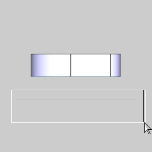
3 Window
pick the Cam Plate.
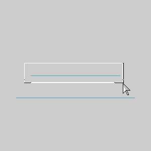
The Preview appears, showing the default settings.
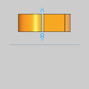
4 Change
the Positive Direction value,
from 1.000 to 0.7500.
The preview updates.
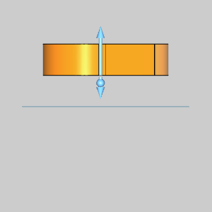
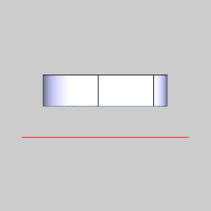
5 Click
OK to confirm the settings and
placement of the Cam Plate.
The Solid is created and an ![]() Extrude Curve feature is added
to the CAD Tree.
Extrude Curve feature is added
to the CAD Tree.
Although our geometry is shown in an isometric view, we will remain, or
return to, a side view in order to make selection easier.
We will create a new CAD layer to keep our imprint separate from the rest of the geometry.
1 Right-click
in the Layers window of the Layer-UCS-Post Manager and select
Add New Layer.
A layer named Not Named is created
and the name is highlighted to allow for alteration.
2 Type
"Soft Jaws" as the name
for the new layer and press Enter,
or click off of the layer to set the name.
3 Click
on the ![]() icon of the new
Soft Jaws layer to set that as
the active layer.
icon of the new
Soft Jaws layer to set that as
the active layer.
The Solid layer is now marked as ![]() active.
active.
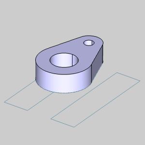
Now that we have a solid model, we can create an imprint of it.
1 In the Solids menu, select Imprint.
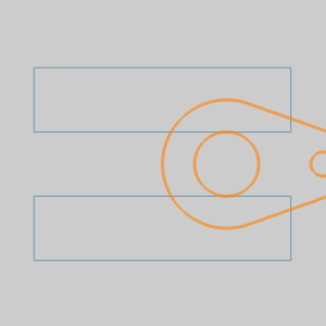
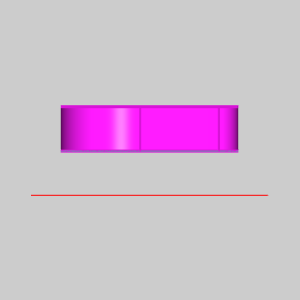
2 By
default, the Profile Chains group has focus and is ready to accept the
geometry we select.
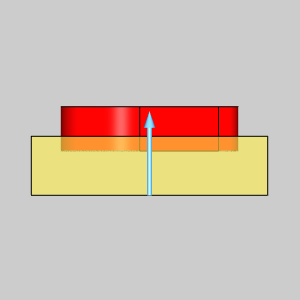
Window pick the Soft Jaws geometry as seen in the image below.
The geometry highlights, and the entities are added to the Profile Chains
list.
3 Click
in the Selected Solids list to
allow us to add our solid to the list.
4 In
the graphics area, hover over the solid to highlight it.
The solid highlights.
5 Click
the solid to select it and add it to the Selected Solids list.
The Preview appears.
 +
+
6 In
the Distance group, change the
option from Default, to the Distance
option.
7 Change
the Distance value to 1.0000.
The Preview updates.
8 Click OK to confirm the settings.
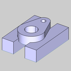
The Imprint is created and an Imprint feature is added to the CAD Tree.
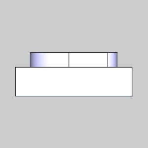
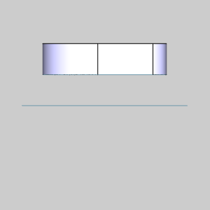
To see what we have created, we will hide the rest of the geometry.
1 In
the View menu, select Views
and choose ![]() ISO 2.
ISO 2.
The View updates.
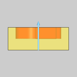
2 In
the Layers window of the Layer-UCS-Post Manager, right-click
the Solid layer.
3 Select
Hide.
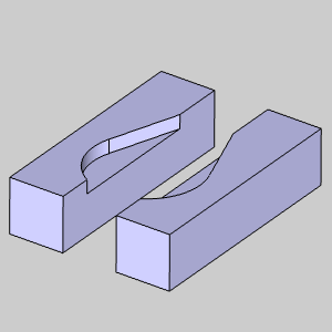
The extruded Cam Plate hides and we can see the result of our Imprint.
This concludes the example.