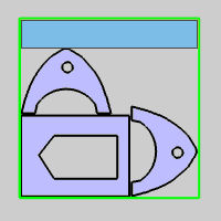
Remnant Sheet Creation example
Introduction
In some cases, nesting parameters result in unused sheet material. Reusing that unused material is an excellent way to eliminate waste. This topic will cover how to export the geometry and reuse that material for another nesting job.
Example File
The BobCAD part file for this tutorial is available in your C:\BobCAD-CAM Data\BobCAD-CAM V**\Examples folder. In the example file provided, the nesting job has already been created.
In this example, you learn how to edit the default remnant shape, adjust the remnant constraints and export the sheet as a .dxf file.
Note: Remnant creation is only available with the Nesting Pro module.
Part 1) Open, Edit and Compute
-
Open the part file Remnant_Sheet.bbcd
-
Right-click on the
 Nesting
Job and select Edit
Nesting
Job and select Edit -
Click on
 Nesting Parameters
on the left of the Nesting Wizard to skip to that page or click Next>> until you get to the
Nesting Parameters page.
Nesting Parameters
on the left of the Nesting Wizard to skip to that page or click Next>> until you get to the
Nesting Parameters page.
-
In the Advanced group, select the check box next to Remnant Sheet to turn on remnant sheets. Click the Remnant Sheet button to open the Remnant Sheet Parameters dialog box.
-
Take a moment to click on each one of the options from the Default Remnant Shape drop down and notice the previews for each to get an idea of the geometry each one will produce.
|
True Shape |
|
|
|
Rectangular |
|
|
|
Stepped |
|
|
|
Clean Cut |
|
|
-
Set the Default Remnant Shape to Clean Cut and click OK.
-
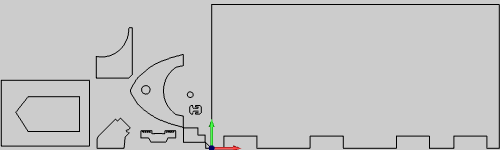
Click Compute to nest the parts, remnants and launch the Remnant Sheet dialog box.
Part 2) Choosing remnant shape and exporting
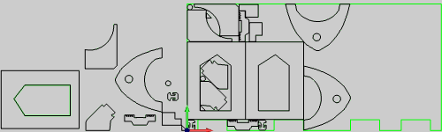
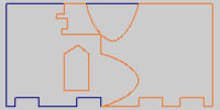
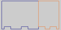
When you compute the nest the Remnant Sheet dialog box will open and
you will be able to preview the possible remnant shape outputs. You can
output the previewed shape to use in other jobs or adjust the preview
by cancelling and adjusting the constraints in the Remnant Sheet Parameters
dialog box. In this lesson we will use the current setting and output
the .dxf file.
-
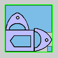
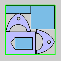
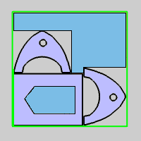
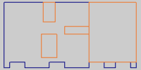
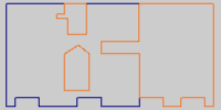
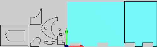
Notice that we have set the default Remnant Shape to Clean Cut. Take a moment to click on each option in the Remnant Shape drop down and notice the preview of the actual shapes they will produce.
|
True Shape |
|
|
|
Rectangular |
|
|
|
Stepped |
|
|
|
Clean Cut |
|
|
-
Set the shape back to Clean Cut.
-
At the bottom of the Remnant Sheet dialog box you will see the Geometry group. In this group you can set the export option to either All Sheets, or Selected Sheet. In this case, both options will accomplish the same thing since we only have one sheet. Click the Export button.
-
The Save As dialog box will open. Select a location to save this .dxf and set the file name to "Remnant" and click Save.
Tip: A copy has been saved in your C:\BobCAD-CAM Data\BobCAD-CAM V**\Examples folder. As such, if you try to save in the same location, you will get a warning about that file name existing already. If that happens, just overwrite the file rather than cancel the save.
-
The Windows Explorer will launch. Notice that our file is highlighted in the list and the name "Remnant" is now "Remnant-Sheet-1-1.dxf".
-
Minimize the Windows Explorer and hit Cancel on the Remnant Sheet dialog box to close it.
Part 3) Opening the DXF and copying into the Remnant_Sheet.bbcd file
-
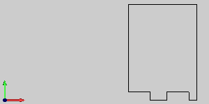
Open the windows file explorer again and drag the .dxf file into the BobCAD-CAM CAD window.
-
Right-click in the CAD window to access the context menu and click Select.
-
Once in selection mode, hold shift and left click the geometry to chain-select it. Once highlighted copy the geometry. This can be accomplished by either selecting
 Copy from the Edit group, of the Home ribbon,
or by using the Ctrl+C keyboard shortcut.
Copy from the Edit group, of the Home ribbon,
or by using the Ctrl+C keyboard shortcut. -
Go back into the Remnant_Sheet.bbcd window and paste the remnant geometry into the Remnant_Geometry layer.
-
Save file.
Part 4) Creating the New Job
-
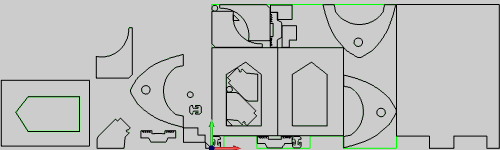
Hide the Remnant_Geometry layer and show the Sheet_Geometry layer.
-
Right-click on the Nesting Job and select Blank/Unblank All to hide the nested parts and toolpath.
-
Right-click on
CAM Defaults
to select a New Job. -
Select Milling for the Job Type and click the Stock Wizard button.
-
Click >> to move on to Stock Type.
-
Select the radio button for Wireframe and click >>.
-
Select the Pick Geometry button, chain-select the Sheet_Geometry and click
 OK to confirm.
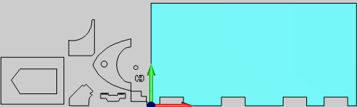
-
Click >> and then OK.
Part 5) Cutting the remnant
When cutting the remnant, it is important to always keep in mind that
a cut will always have a width to it. To get the most of the remnant,
we would always want to compensate for our tool width on the outside of
our remnant. Depending on the nested result and the size of our tool,
that cut may have an effect on our nested parts. In this case we will
cut down the center of the line with a tool that will not interfere with
the parts on the sheet. This will only have a small affect on the remnant.
-
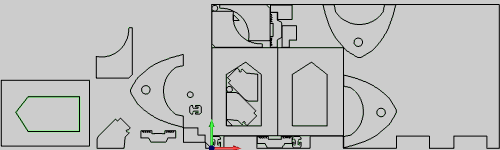
Hide the Sheet_Geometry layer and make the Remnant_Geometry layer visible.
-
Right-click on
 Machine
Setup-1 and select Mill 2 Axis.
Machine
Setup-1 and select Mill 2 Axis. -
Click on the Select Geometry button to hide the Mill Wizard and enable selection mode.
-
Click on the line on the left side of the remnant and click
OK to confirm.
-
Click Next>> and set the Total Depth to 25.4.
-
Click Next>> and remove the Profile Rough from Current Operations.
-
Click Next>> three times to get to the
 Finish page. Set the
tool Diameter to a value of 6.3500.
Finish page. Set the
tool Diameter to a value of 6.3500. -
Click Next>> and set System Compensation to Off.
-
Click on
Leads in the
Feature tree on the left of the Mill Wizard to jump to the Leads page or click Next>>
until you reach the Leads
page. -
Set lead to Parallel.
-
Click the Compute button.
Using the Remnant
Now that the Remnant has been decided upon, exported, brought into the nesting file and cut, you will have two jobs to post code for. The first is the initial nest and the second is the code to cut the remnant sheet free. In the next lesson, we will be Using the Remnant sheet to create a nest for other parts.