Flowline
Introduction
The Flowline toolpath creates a pattern of parallel cuts following the UV curves of the selected surface. This toolpath has simplified geometry selection, meaning it only requires a single drive surface to create the toolpath (no other selections are needed). This allows you to create flowline-style toolpath quicker than the other Multiaxis toolpath types.
Surface Paths
Pattern
-
Drive surface - enables selection mode for you to select the Drive Surfaces geometry. The toolpath is applied to the normal side of the surface.
Note: You can select more than one surface for this feature. When multiple surfaces are selected, the toolpaths for each surface are calculated individually and then combined.
-
Drive surfaces offset - is used to leave stock remaining on the part. You can use positive or negative values.
-
Flow direction - determines the toolpath direction on the surface using either Long side or Short side. The software utilizes the UV lines of the selected surface to determine the toolpath direction. The UV lines are always perpendicular to each other and these are the only two possible directions for the toolpath.
To learn about the remaining Surface Paths parameters, view Surface Paths.
To learn about the other Multiaxis Parameters, view the Multiaxis Wizard.
How it Works
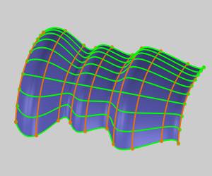
The Flowline toolpath uses the UV lines of the selected surface to determine the general toolpath direction. The following image shows the UV lines for the example part using green and orange. Notice the lines are perpendicular to each other.
UV Lines
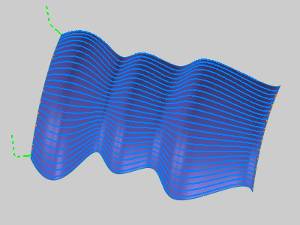
Long side Toolpath
When you compute the toolpath using the default Along, you get the following result.
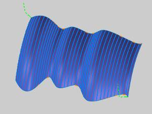
Short side Toolpath
When you compute the toolpath after changing to Around, you get the following result.