Morph Between Two Curves
Introduction
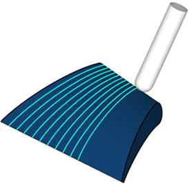
The Morph Between Two Curves feature creates a morph toolpath between two leading curves. Morph means that the generated toolpath gradually interpolates between the two curves and it is evenly spread over the surface. This option is very suitable to machine steep areas for mold making. When selecting the two curves, generally, the geometry is selected directly from the drive surfaces.

Surface Paths
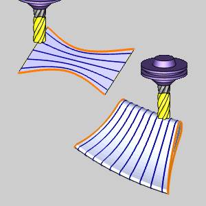
The Morph Between Two Curves feature requires two lead curve selections and a Drive Surface selection. As shown in the previous image, the orange lines are the two lead curves and the surface is the Drive Surface. In the Multiaxis Wizard, the Pattern parameters of the Surface Paths tab are shown next.
Pattern
Edit curves
- First - enables selection mode for you to select the first curve geometry.
- Second - enables selection mode for you to select the second curve geometry.
-
Drive surfaces - enables selection mode for you to select the Drive Surfaces geometry. The toolpath is applied to the selected surfaces.
-
Drive surfaces offset - is used to leave stock remaining on the part. You can use positive or negative values.
To learn about the remaining parameters used with Morph Between Two Curves, view the Surface Paths.
To learn about the other Multiaxis Parameters, view the Multiaxis Wizard.
Tip:
• This functionality works better
if the two curves lie accurately on the drive surface. So the best
result would be an exact curve on the edge of the drive surface.
• Determined by Number of Cuts: the number
of the cuts is not clearly defined in this strategy since you have
a morph toolpath and the distances between two adjacent toolpath segments
at the end of the faces may be different.
• When you set the cutting area to Full,
Start and End at Exact Surface Edge you can set margins to the curves.
• The first slice is always at the first
curve, the last slice at the second curve. The progress can be flipped
by activating Flip Step Over.
• The direction of the input curves defines
the cut direction (clockwise/counterclockwise). If the direction of
the input curves is clockwise, the toolpath is calculated clockwise
as well.
Example
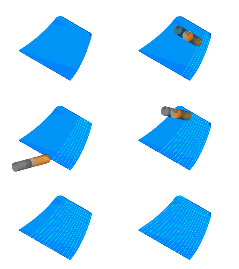
In this example you see a cut out of a wing. The black lines on the edge of the sides are the selected curves. As you can see the angle between these curves as well as the shapes are totally different. The generated toolpath is approximated between the two guide curves and evenly spread on either side. Now compare to parallel cuts toolpath, you can see that the toolpath segments are evenly spaced, there can be small segments at the corners. The advantage of parallel cuts is an even cusp left after finishing. In morph toolpaths the cusp varies.


