Project Curves
Introduction
The Project Curves feature is used to create projected toolpaths using either a user-defined geometry curve, offsets of that curve, a radial pattern, or a spiral pattern. When selecting curve geometry directly from a surface, the projected toolpath is identical to the original. When the curve geometry is above the surface there are multiple possible results depending on the scenario and parameter selections. This pattern can be used to create engravings as well as spiral or radial finishing patterns for complete surfaces.

Surface Paths
Pattern
Edit curves
-
Projection - enables selection mode for you to select projected curve geometry. This is only available for the Types, User Defined or Offset.
-
Projection direction - select from one of the following options.
-
X-axis - projects the curve along the X-axis.
-
Y-axis - projects the curve along the Y-axis.
-
Z-axis - projects the curve along the Z-axis.
-
Line - when selected, click
 to
open the Projection
Line dialog box. You
can type coordinates, or click to select geometry along which the
curve is projected.
to
open the Projection
Line dialog box. You
can type coordinates, or click to select geometry along which the
curve is projected. -
Surface normal - projects the curve in the surface normal direction. When this option is selected, the Maximum Projection Distance becomes available. This option is only available when the Type, User Defined, is selected.
-
Max. projection distance - controls how far the curve can be from the machining surface. Anything beyond this distance is not included in the projection.
-
Drive surfaces - enables selection mode for you to select the Drive Surfaces geometry. The toolpath is applied to the selected surfaces.
-
Drive surfaces offset - is used to leave stock remaining on the part.
-
Cutting Side - defines the tool compensation setting for the feature as Center (none), Left, or Right. When using Left or Right, you may need to modify the start point direction (of user-defined projection curves) to properly create the feature.
-
Cutting Side Offset - adds an additional offset of the toolpath from the projection curves. This is only used with the Cutting Side parameter set to Left or Right.
-
Type
-
User defined - means that the projection curve is user defined (not Radial, Spiral, or Offset). Click Projection (Edit Curves group) to select the projection curve geometry from the graphics area.
-
Radial - creates a radial pattern that is projected to the Drive Surface. The following options become available.
-
Center point - defines the center of the radial projection pattern using one of the following options.
-
Autodetect - allows the software to automatically find the center of the radial pattern (based on the selected Drive Surface).
-
User Defined - allows you to type coordinate values for the center point of the radial pattern (as distances from the machining origin of the part). You can also click
to open the Pick
dialog box, and then click Pick to select geometry from the
graphics area to set the center point of the radial pattern. -
Radius - type values for the Start (inner) radius and the End (outside) radius of the radial pattern. For the End radius, you can select User Defined and type the value, or you can select Autodetect and allow the software to attempt to automatically create the End radius.
-
Angle - type values for the Start angle and End angle used for the radial pattern (from the X-axis).
-
Spiral - creates a spiral pattern that is projected to the Drive Surface. The following options become available.
-
Center point - defines the center of the spiral projection pattern using one of the following options.
-
Autodetect - allows the software to automatically find the center of the spiral pattern (based on the selected Drive Surface).
-
User Defined - allows you to type coordinate values for the center point of the spiral pattern (as distances from the machining origin of the part). You can also click
to open the Pick
dialog box, and then click Pick to select geometry from the
graphics area to set the center point of the spiral pattern. -
Radius - type values for the Start (inner) radius and the End (outside) radius of the spiral pattern. For the End radius, you can select User Defined and type the value, or you can select Autodetect and allow the software to attempt to automatically create the End radius.
-
Offset - this option allows you to create an offset to the selected projection curve. The following options become available:
-
Number of cuts (left) - type the number of times the curve is offset to the left of the projection curve when Left or Both is selected for the Step Direction.
-
Number of cuts (right) - type the number of times the curve is offset to the right when Right or Both is selected for the Step Direction.
-
Step direction - controls in which direction the offset can be created. Select Left, Right, or Both to define which direction the toolpath is created from the selected projection curve.
-
To learn about the remaining Surface Paths parameters, view the Surface Paths.
To learn about the other Multiaxis Parameters, view the Multiaxis Wizard.
Example
-
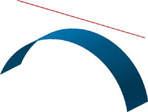
A simple curved face with a projection curve (red) above. The curve lies within the max projection distance.
-
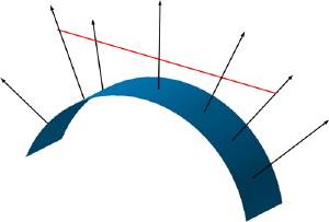
For the projection, some surface normals (black) intersect with the curve.
-
Only the intersecting surface normals are used for the projection.

-
The curve projected onto the drive surface.

-
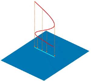
A vertical spline curve projected onto the drive surface creates a line.