Defining the Machine Setup
Introduction
This topic describes using the Machine Setup dialog box after defining stock, and also provides links to related topics.
The Machine Setup
The Machine Setup has two important components: the Machine Setup dialog box and the Machine Setup item in the CAM Tree. The Machine Setup dialog box is used to define the machining origin (or work offset) and the clearance plane for all features that are added to the Machine Setup in the CAM Tree. This is critical to creating correct toolpaths and NC programs. The Machine Setup item in the CAM Tree is used to edit the previously defined Machine Setup parameters and create CAM features.
Important: It is important to understand that when creating CAM features, the machining origin (Machine Setup) defines the machining coordinates and not the WCS (or the world coordinate system) of the graphics area.
Initial Setup
Before you define a Machine Setup for any part, you must first create stock geometry for the part. After the stock has been defined, clicking >> (Next) will take you to the Machine Setup dialog. This dialog allows you to alter the default position and orientation of the machine setup as needed. Clicking OK will finalize the setup.
Select the Machine Setup
- The Machine Setup group at the top of the dialog box lists all the
 Machine Setup items currently in the
CAM Tree.
Machine Setup items currently in the
CAM Tree.
Click the Machine Setup arrow, and select the appropriate setup from the list.
- For Mill Turn jobs, you must also select Left Spindle or Right Spindle to determine the spindle to which the machine setup is assigned.
How to select the Machining Origin
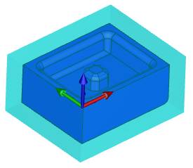
The Machine Setup dialog box is used to set the machining origin or work offset for the part on the machine. When this dialog box is opened, the stock shows the bounding box made of lines and points. These lines and points are automatically created, for your convenience, to use when setting the machining origin. By default, the machining origin is located at the WCS or world coordinate system (X0 Y0 Z0) as shown next.

The previous image has shading turned off to better show the bounding box selection entities.
-
If you want to use the top and center of the stock as the machining origin, click Reset to Stock Coordinate.
This uses the stock origin from the Stock Definition dialog box.
-
To change the machining origin to a different location, in the
Once you pick a point, the machine setup is automatically moved.


Tip: The bounding entities that are created in the Machine Setup dialog box are for your convenience in setting the machining origin. You are not limited to using these entities when setting the machining origin. To alter the alignment of a particular axis, click in its list box to give it focus, and then select an entity in the graphics area. Selecting a line will set the axis parallel to it. Selecting a point will direct the axis along the line formed between its zero and the selected point.
-
The machining origin is now set to the lower-left corner on the top of the stock.
- Set the Work Offset to describe the difference between the selected machine setup, and the machine zero.
- Set the Clearance Plane to be used for the job.
- To finish the Machine Setup, click OK.
You are now ready to create CAM features.
How to set the Machining Origin using the Enter Method
-
In the Origin group,
The values are from the WCS. -
The default directions of the Machining Origin follow that of the WCS.
-
To change the direction of one the coordinate system axes, click
 next to X Direction, Y Direction, or Z Direction to reverse the positive
and negative direction of the corresponding axis.
next to X Direction, Y Direction, or Z Direction to reverse the positive
and negative direction of the corresponding axis.
How to set the Machining Origin using Pick From Existing UCS
-
In the
Other Settings
This group provides default settings that are used for all features under the selected Machine Setup in the CAM Tree.
-
Work Offset - opens the Work Offset dialog box. Select the Work Offset # used for this Machine Setup. All milling features that are added to the selected Machine Setup use this value as the default.
-
The X, Y, and Z boxes are used to define the distance from the machine zero to the selected Machine Setup coordinate system. An example of this is shown in the next image.

-
Clearance Plane - sets the value used for the clearance plane in all milling features created under the selected Machine Setup. This is the safe rapid distance between operations as an incremental value from the top of stock for the program.
Mill Turn Clearance Settings
If you are creating a Mill Turn job, the Clearance button displays in the Machine Setup. Click the Clearance button to open the Clearance Dialog Box for Mill Turn jobs.
To finish the Machine Setup, click OK.
Subsequent Setup
Once stock has been defined, and the Machine Setup item has been created in the CAM Tree, right-clicking Machine Setup, and clicking Edit will take you back in to the Machine Setup dialog box in the Data Entry Manager.
Important: If you move the machining origin of a Machine Setup that contains existing features, you need to re-confirm the geometry selection and compute the toolpath to update the change. Right-click the Machine Setup and select Update All Geometries (In milling jobs, this is found under Additional Functions). Once the geometries have been updated, you will need to recompute the toolpaths (In lathe jobs, recomputing is done automatically).
Multiple Setups
To create multiple Machine Setup items (Mill and Mill Turn only), in the CAM Tree, right-click Machine Setup, point to Additional Functions, and click Insert Setup. This adds another Machine Setup below the previous. Both Machine Setup items are then available for selection in the Machine Setup dialog box.
Related Topics
How to Create Multiple Machine Setups