Morph Between Two Surfaces
Introduction
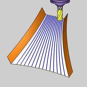
The Morph Between Two Surfaces feature creates a morph toolpath on the drive surface. The drive surface is enclosed by two check surfaces. Morph means that the generated toolpath is approximated between the check surfaces and evenly spread over the drive surface. This is great for impeller machining with twisted turbine blades. The main advantage is the possibility to compensate the tool to the drive surface and check surface in the left and right corner of the work piece. This is accomplished using the tool radius which is the distance (Margin) between the tool center and the surfaces.

Surface Paths
Pattern
Edit surfaces
-
First - enables selection mode for you to select the first edge surface geometry.
-
Second - enables selection mode for you to select the second edge surface geometry.
-
Drive surfaces - enables selection mode for you to select the Drive Surfaces geometry. The toolpath is applied to the selected surfaces.
-
Drive surfaces offset - is used to leave stock remaining on the part. You can use positive or negative values.
-
Advanced - opens the Advanced Options for Surface Paths dialog box.
To learn about the remaining parameters used with Morph Between Two Surfaces, view the Surface Paths.
To learn about the other Multiaxis Parameters, view the Multiaxis Wizard.
Example
- This example shows an impeller section that uses Morph Between 2 Surfaces.

