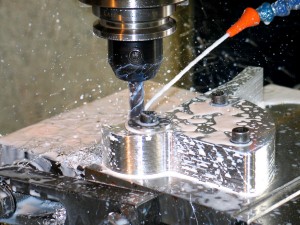
For many machine shops, quality CAM software ranks as important as having powerful machines and sharp tools. It’s all about getting the job done efficiently and in profitable way. As machining capabilities have advanced, so too has the complexity of CNC programming. Manually programming advanced multi-axis jobs just isn’t practical. Instead, companies have come to rely on CAM software to provide the means to not only efficiently program their machining jobs, but also to visualize the process and detect problems through simulations. The features that make complex machining possible also trickle down to make less complex machining easier, more efficient and ultimately more profitable.
 Before I give the impression that CAM software is only vital for shops with complex machining operations, let’s circle back to the important aspects of machining we touched on above: efficiency and profitability. A lot of shops struggle with the balance of churning out precisions parts in a timely and cost-effective way. This can be observed in a number of ways, including: constantly having to re-machine parts due to costly part gouges or collisions, labor hours involved in programming a CNC machine for each part eats into your profit margin, or you’re turning away work that you’re not capable of taking on. Adding CAM software to any shop’s machining capabilities can make the difference between a profit and a loss.
At the end of the day, nearly all CNC machine shops can realize positive gains by utilizing easy-to-use and powerful CAM software. Understanding how CAM software works can give you a better idea of what areas it can potentially impact in your business.
CAM Software Step-By-Step
Importing To CAM Software
Getting started with CAM software, you’ll likely be starting with a 3D model of a part that either you designed in your CAD software or your client designed and they’re sending you their file. There are a couple important aspects to consider when importing a part file into your CAM software:
1. Does your CAM software support the file format.
2. If it’s supported, does the CAM software correctly translate the file data so that there aren’t any geometry or surface issues? Even if this issue does arise, it’s typically correctable – it just goes back to the efficiency element.
CAD design programs typically have their own native file type, such as the SolidWorks SLDPRT format or AutoCAD’s DGN. Other common file types are STL, STEP, IGES, and DXF.
An alternative to working in separate CAD and CAM software programs is to use a combine CAD-CAM system, like BobCAD-CAM. The benefits to this include:
1. Seamless transition from part design in CAD to developing machining operations in CAM.
2. Easily revert back to CAD for any part edits that take place during production.
Additionally, if you need to make any adjustments to your client’s part file, CAD-CAM software can greatly enhance the workflow efficiency during file translation, geometry verification, and any part file edits that are needed.
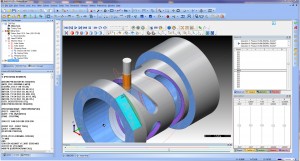
Using CAM Software to Structure Your Job
Once your part is ready for toolpaths and programming, you’ll find that most CAM software products provide a standard “Job Tree” structure for organizing the machining strategies. The job tree provides a clear overview of your machining process which is visible in a format that is similar to the way your PC organizes its drives and folders. This allows you to easily locate and inspect machining operations, edit tools & toolpaths, turn on/off operations, and reorder the machining sequence for greater efficiency.
Initially, you’ll set up and save the features of the machine from your shop within the CAM software. This way, you’re developing programs specific to your machine, whether it’s 2, 3, 4, or 5-axis capable. Once your machine is saved, you can easily select this machine for future projects and edit the machine settings, as needed.
Next, you’ll identify your stock which is your raw component, prior to any machining. This allows you to set up initial work coordinates, material type, and the tools to be used. Each of these affects the speed and feed settings within toolpath strategies, which will become important in calculating cycle times.
 Properly inputting all this data is critical – using a CAD-CAM software, like BobCAD-CAM, that uses wizard guiding systems can greatly improve workflow efficiency by automatically prompting you to enter this information every time so there aren’t any accidental omissions.
In addition, you’ll also set up your cutting conditions, tool patterns, tool crib, and tool holder data. All of this is vital to creating error-free CNC programming. Your tool library should include all tool data, material, diameter, angle, length, and more as this is important for your machining strategies within your job tree manager.
The great thing about CAM software is that you’ll be saving all of this information to your system. Knowing that many shops tend to take on jobs that are similar in nature, there is a huge potential to speed up or eliminate redundant programming steps. Instead of having to start from scratch for each job, your CAM software allows you to easily load tools and machine features from previous jobs for future projects, which adds up to a huge time savings and efficiency boost.

Setting Your Toolpaths within CAM Software
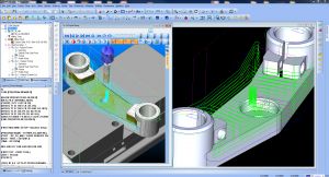 Once you’ve identified your starting points (machine, tools and stock), you’re ready to move onto developing your machining operations. Starting with your stock, you’ll decide on toolpaths for your roughing and finishing cycles to ultimately achieve your desired part design. This is where your job tree manager will assist you in keeping your machining operations organized and properly sequenced.
When you’re using software like BobCAD-CAM, you’ll have the benefit of machining wizard guides, which act as a series of dialog boxes that step you through the process until you’ve properly set up the toolpath.
Wizard guides are amazingly helpful for a couple reasons:
1. New users can create programs in a fraction of the time since they’re being prompted for the information the program needs to generate the toolpath.
2. Even experienced users can forget a step, but wizard guides are a sort of fool-proof way of making sure all of the necessary information is provided.
The toolpath wizards allow you to select the areas of the part to apply a specific toolpath (planar, spiral, z-level, etc.) within a boundary or the entire part, and set clearances & height of rapid moves for the tool. You’ll also select the type of cutting pattern (zig-zag or single direction), cutting direction (climb or conventional), roughing parameters, custom tolerance and cut-depth options, lead-in/lead-out options, toolpath linking options, and other machine options.
Some CAM software offers the ability to program High Speed toolpaths. These differ from traditional hard right and left turn toolpaths. Instead, they are more rounded cutting motions which create a more constant tool engagement (less tool-material collisions). Greater tool engagement is proven to extend the life of cutting tools.
CAM Software Simulators
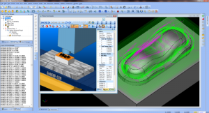 Once you’ve create a toolpath for each operation, you’re ready to move onto simulation. A quality simulation program allows you to visually inspect the machining program you’ve just created in a realistic virtual environment.
The goals of simulations are:
1. Analyze part deviations – the CAM software generally identifies these by a color scale based on deviation tolerance levels.
2. Identify costly gouges or collisions during the error detection stage
3. Calculate cycle times
Post Processing
Once you’re happy with your operation, it’s time to export the CAM software program to g-code, which is the NC file that is readable by the CNC machine. Every machine is different, so each machine’s g-code can vary. That’s why it’s important that you have the proper g-code post processor added to your CAM software. These can generally be provided by your control manufacturer, your CAM software provider or if you’re comfortable, you could modify your post processor to fit your machine.
What to Look For When Selecting CAM Software
CAM software has the potential to significantly impact a shop’s productivity and profitability. Here are a few must-haves features we suggest you look for when evaluating CAM software options:
1. It should be easy to use. Get something that is easy for you to learn and easy for new operators to learn down the road. Evaluate what training resources are made available by the CAM software company – do they offer training seminars, online training, webinars, or video tutorials? The more resources at your disposal, the easier it will be to learn in a way that works for you.
2. It should be versatile. It may be easy to find a software that works for you today but you’ll want something that you can grow with. Think of where you might be in 5-10 years and know if there is room to grow with the software.
3. It should be powerful. Make sure that the CAM software has advanced toolpath strategies that provide a significant improvement to your workflow efficiency and reduce your cycle times.
4. It should be affordable. Advanced functionality is no longer reserved for excessively expensive CAM software.
Other related CAD-CAM articles that you may be interested in:

Summary
Article Name
CAM Software for Manufacturing CNC Machining
Description
With the advancement of CNC machining, CAM software has become a vital tool for shops that produce both complex and simple parts. Learn how CAM software is making shops more efficient and profitable.
Author
Nick Erickson | BobCAD-CAM