Multiaxis Wireframe
Introduction
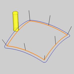
The Wireframe toolpath type uses a Drive Curve (wireframe geometry) to create a toolpath with the tool orientation controlled by Orientation Lines. This is designed for 5-axis profiling. Further control of the tool orientation is provided in the Tool Axis Control tab. This help topic explains the Multiaxis Wizard parameters that are available when using the Wireframe toolpath type.

Surface Paths
Pattern
Edit Curves
-
Drive curves - enables selection mode for you to select geometry from which the toolpath is created. (The curves define the path.)
-
Orientation lines - enables selection mode for you to select geometry that is used to set the tool orientation along the drive curves. After selecting the curves in the wizard, you must set the chain direction for each orientation line using the CAM Tree, as explained in the Multiaxis Wireframe tutorial.
-
Maximum snap distance - controls what orientation (tilt) lines are used for the toolpath calculation. Any tilt line beyond this distance from the Drive Curve is not used.
-
Machining side - defines the cutting side of the drive curve in relation to the chaining direction.
-
Left - cuts on the left side of the forward direction for open drive curves.
-
Right - cuts on the right side of the forward direction for open drive curves.
-
Center - cuts directly on the drive curve.
-
Inside - cuts the inside of the shape for closed drive curves.
-
Outside - cuts the outside of the shape for closed drive curves.
-
-
Additional Offset - creates a minimum distance between the toolpath and the selected drive curve.
Area
For all of the following options, you must select the check box to turn on the option, and then click the button to access its parameters. Click the links to view explanations.
-
2D Containment - is used to project a 2D curve in which the toolpath is contained.
-
Round corners - provides an additional radius value used for creating round corners.
-
Extend/Trim - is used to extend or trim toolpaths based on the defined values.
Sorting
-
Enforce Cutting Direction (Assume Closed Contours)
 Select the check box to use open contours and create a toolpath as if
the geometry is closed. This option is not available when using Follow
Chain Curving.
 Clear the check box when creating toolpaths with open contours.
 -
Direction for one way machining - controls how the tool cuts into the part: Counterclockwise, Clockwise, Follow Chain Curving. The last option uses the wireframe chaining direction.
-
Start point - for wireframe is by Position only.
 Select the check box when specifying a toolpath starting point. Click
Start Point to open the Start Point Parameters dialog box. Click
  to open the Point dialog box. You can type coordinate
values, or click Pick to select the start point geometry.
 Clear the check box to allow the software to
define the starting point.
Surface Quality
-
Cut tolerance - determines how accurate the toolpath must be in relation to the selected geometry.
-
Maximum distance - controls the greatest distance between toolpath points.
Tool Axis Control
The Tilting Strategies for the Wireframe toolpath type are slightly limited compared to the surface based features. These options are all explained in Tool Axis Control.
The following Tool Axis Control parameter is unique to the Multiaxis Wireframe toolpath. This option is only available when the tilting strategy is set to Tilted Relative to Cutting Direction.
- Tilt Away from Line - determines the amount of side tilting applied to the tool orientation. With a value of zero degrees, the tool orientation is the same as the selected Orientation Lines. A value of ninety degrees creates a tool orientation that is perpendicular to the selected Orientation Lines.
Gouge Check
To learn about gouge checking, view Multiaxis Gouge Checking.
Link
To learn about defining lead-in, lead-out, and clearance parameters, view Multiaxis Links.
Roughing
To learn about all options found on the Roughing tab, view the Roughing Tab.
Utility
To learn about all options found on the Utility tab, view the Utility Tab.
