Wireframe Series: Installment 2 of 2
 The ability to extract wireframe geometry from a solid or surface in CAD/CAM software is vital to CNC programming. In our previous wireframe installment, we covered the areas in which wireframe offers the control and efficiency needed for model inspections, existing part modifications, and toolpath boundary adjustments. In this installment we cover the actual methods you can use to extract wireframe geometry from a solid or surface.
Note: It’s always a good idea to create a new layer and make it active when working with wireframe. It’s important to do this since you’ll want to be able to separate the wireframe from the surfaces and solids. It’s just a quick and easy way to achieve this.
Try these tools for yourself as you read this article – CLICK HERE to download a free trial copy of high performance CAD/CAM software now.
EXTRACT EDGES
 Single
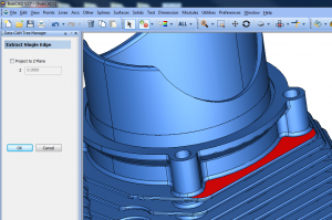
This feature allows you to select a surface edge, single surface, or multiple surfaces from which you would like to generate wireframe. This method is great for isolating surfaces that you want to work with. In the BobCAD-CAM software you’ll find this under the “Utilities” menu > Extract Edges > Single. Once selected, the “Extract Single Edge” menu will display on the left of your screen. This menu contains an option to “Project to Z Plane.” This feature allows you to select a Z value to project the wireframe geometry on as opposed to extracting at its location on the part model.
 From Solids
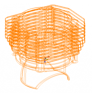
This option differs from Extract Edges Single in the sense that you’ll select your solid and it will extract ALL of the wireframe from your solid. You’ll find this option under the “Utilities” menu > Extract Edges > From Solids.
There are certainly advantages to generating a complete wireframe of your solid but you may find it easier to work with smaller sections of your parts using the Extract Edges Single option when dealing with complex solids in CAD/CAM software.
SECTION VIEW
 Section view can be found under the “View” menu > Section View
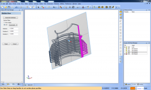
Once you select the Section View tool, a plane is generated on your part. Wherever that plane intersects with your solid, the CAD/CAM software displays a preview of the intersecting section in pink. The “Section View” menu on the left side of your screen will display a button called “Generate Wireframe” which is a quick and easy way to generate the desired wireframe geometry from the intersecting sections.
This is a great tool to view internal features and for general inspection. You can also use it when you’re generating your OD and ID profiles for your parts that you’re going to turn.
Surface Intersection Curves
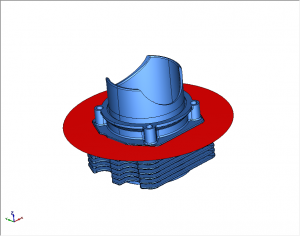 In order to use this feature, you need two surfaces or solids that intersect with each other. If you’re working with one solid, you can create a separate surface that intersects with your solid to utilize this tool. As an example, you could go to the “Surfaces” menu and select a Circular Plane to generate a surface that you can set to intersect with the model.
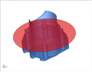 From here you would go to “Surfaces” menu and select Intersection Curves. After selecting the newly created surface and the solid, the wireframe will be extracted from the area of intersection. One of the great things about using this feature is that it allows us to take the surface plane and translate it down. Meaning we can repeat this process at a different level of the solid quickly and easily.
The most effective and easy method out of these three will really depend on what geometry you’re looking to capture and your comfort level with the tool. Each offers an incredibly powerful way to extract wireframe geometry. Additionally, having multiple ways to achieve the desired result is generally a good indicator of a quality piece of software.
To explore using these tools on your part models, download a free, no obligations trial copy of BobCAD-CAM software. CLICK HERE TO DOWNLOAD
In the end, Computer Aided Design software continues to offer powerful features that allow engineers and manufacturers to prepare their solid models for toolpath and CNC machine g-code more efficiently than ever before. BobCAD-CAM offers hundreds of unique time saving features for CNC machining. Try a free demo today!
Here are some other articles you may be interested in:


Summary
Article Name3 Easy Ways to Extract Wireframe in CAD/CAM Software
DescriptionLearn three easy methods to extract wireframe geometry from a solid or surface using CAD/CAM Software.
Author
Nick Erickson | BobCAD-CAM