Questions? Call Us to speak with a CAD CAM Pro!
Welcome to our blog where we dive into the fascinating world of 3D modeling! Today, we’re embarking on an intriguing journey to create complex 3D cad surfaces using some basic yet powerful functions. Our focus? Constructing an impeller.
Part 1: Laying the Groundwork
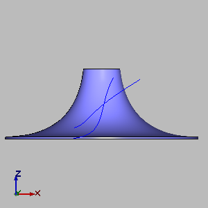
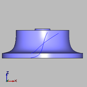
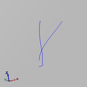
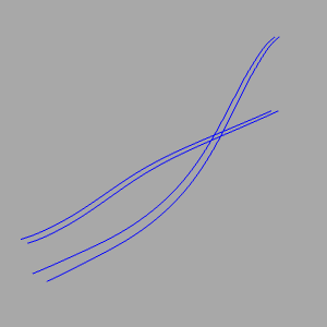
Our first step in this exciting project involves creating a revolved base to which the blades will be attached. This base, along with a revolved outer shell, sets the boundaries for our blades. We’ll also draft a flat cross-section of the blade’s base and outer edge from a side view, providing us with a guide to project onto our surfaces later. Once we have these foundational elements, we will project the bottom of the blade onto the main revolved surface and the blade’s outer edge onto our outer shell. This projection process gives us a 3D wireframe, setting the stage for the actual blade construction.
| Revolved Base |
Revolved Shell |
Projected Wireframe |
 |
 |
 |
.
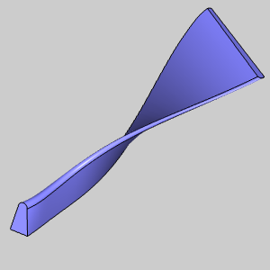
Part 2: Shaping the Blades
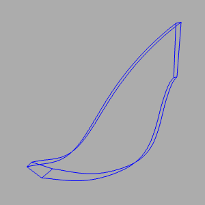
Now, with our edges defined, we can start shaping our blades. By revolving these edges and creating a copy, we add width to our blades, crucial for their structural integrity. You’ll notice that the blade’s base is revolved slightly more than the leading edge, providing additional thickness where it’s most needed. The next step is straightforward yet pivotal – connecting these edges with lines to outline the blade’s shape.
| Projected Wireframe |
Revolve |
Result |
|
 |
 |
..
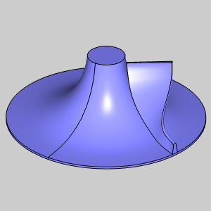
Part 3: Organizing and Surfacing
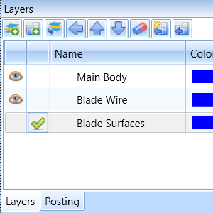
With all necessary edges in place, the next move is to streamline our workspace and flesh out the surfaces. I’ll create a new layer, which will be hidden, to keep the surfaces out of sight as soon as they are built. This approach not only keeps the workspace tidy but also simplifies the surface creation process by removing them from the selection area, so shared edges can be selected with ease. It’s an efficient way to manage geometry and stay organized.
| Hidden Active Layer |
Preview |
Result |
 |
 |
 |
..
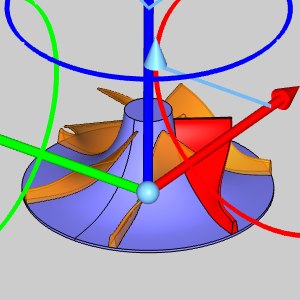
Part 4: Assembling the Impeller
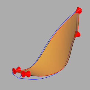
The final phase involves replicating the single blade we’ve created, revolving these copies, and attaching them to our revolved base. In the accompanying blade image, you’ll notice an extra detail – a filleted surface at the leading edge of the blade, enhancing the design’s functionality and aesthetics. With the blades in place and rotated, our impeller model stands complete.
| Completed Blade |
On Revolved Base |
Revolve |
 |
 |
 |
.
Conclusion:
In wrapping up, this project exemplifies how basic functions, when applied creatively and methodically, can yield complex and functional 3D models. From the initial revolved base to the detailed blades and their strategic positioning, every step has been crucial in bringing our impeller from concept to reality. This process not only highlights the importance of detail in 3D modeling but also demonstrates how organization and methodical steps lead to efficient and successful outcomes. Whether you’re a seasoned modeler or just beginning, this journey through creating an impeller offers valuable insights into the intricate yet rewarding world of 3D design.
.
Questions? Call Us to speak with a CAD CAM Pro!