Wireframe Series: Installment 1 of 2
One of the most useful functions within CAD-CAM software for CNC Mill is extracting wireframe from a solid or surface. It offers an easy way to inspect part models, manipulate solid and surface model geometry, and adjust toolpath boundaries quickly.
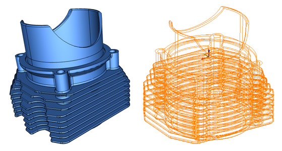
Aside from wireframe, some CAD-CAM software lets you work with surface edges. This is very useful but can potentially be a bit of a slower process since it requires you to manually select individual surface edges. And in some cases, surface edges may not allow you to select the geometry that you need. That’s an easy situation where wireframe can help.
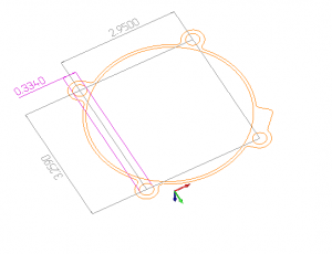
An example of where you would need to extract wireframe would be if your model has two drill holes and you want to measure the distance between the centers of each of these holes. You would need to use wireframe to capture this measurement since the centers of these holes don’t have surface edges available to select.
Ultimately it boils down to individual scenarios to see which method is going to provide the quickest and easiest solution for you. It’s best if you can use software that offers both methods.
The new BobCAD-CAM software now offers surface edge technology so you’re able to work with whichever method you prefer. Click here to see for yourself!
Here is a list of processes that are made easier through the extraction of wireframe geometry:
Inspection
As is common with many machine shops, the majority of CNC programming jobs come in from clients that supply their own part files. When the part file is received, the first step is typically your inspection process. This is where you’re going to want to go in and confirm part specs and measure out holes, distances, and other crucial data of the surfaces and solids to properly machine the part. Even if your client supplies a design print that lists all the measurements, you’ll still need to confirm the part model accurately reflects this information.
Making Modifications to an Existing Part Model
Once you have your client’s file, you may notice that changes to the model are needed to properly manufacture the part or the client may request modifications to the part on future orders. Working with wireframe makes it easy to go in and quickly make part alterations. It’s not always possible to easily select the geometry that you need when working with surfaces edges so wireframe can be incredibly useful when this situation arises.
Adjusting Toolpath Boundaries
When you get to CAM toolpath programming, you may find that your default toolpaths aren’t capable of cutting the material you need. So you need to make adjustments to the targeting geometry that you’re working within.
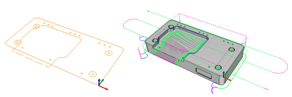
Take for example when you’re in CAM for CNC programming and need to machine a 2D open pocket. No matter what toolpath you choose, your tool may leave a thin layer of material that should have been removed to create the “open” section of the pocket. To correct this, you could use wireframe geometry to grab the pocket geometry and extend the toolpath boundary past the wall so that the tool properly creates the open pocket of the part model.
Extracting wireframe geometry from solids and surfaces is one of the most useful functions of CAD/CAM software for CNC programming. Understanding the usefulness of this feature can go a long way in making CNC machining jobs easier and more efficient. The second installment of our Wireframe series will cover three easy ways to create wireframe from a solid or surface in CAD/CAM software – Read it HERE.
Experience the power of wireframe extraction today – Download a free demo of the new BobCAD-CAM software for CNC Mill HERE
Summary
Article Name
Streamline 3D Modeling with Wireframe in CAD-CAM Software
Description
Find out why extracting wireframe from a solid or surface is one of the best ways to work with 3D geometry in CAD-CAM software for CNC Mill.
Author
Nick Erickson | BobCAD-CAM