Introduction
This version of BobCAM for SolidWorks V7 offers more functionality than ever before. This version has 86 upgrades and enhancements affecting the following areas:
- NC Editor : New NC Editor
- Language : Now available in German and Russian
- General CAM
- Milling
- Mill Turn
- Posting
- Simulation
New G-Code Editor
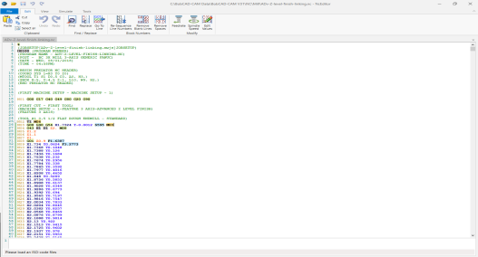
It has been quite some time since the NC code editor has seen an enhancement, and we are proud to introduce the new NcEditor product into the BobCAD-CAM product line. This product was developed to make your code editing and review much faster and more efficient, as well as provide the ability to simulate your NC programs directly!
The NcEditor Standard product comes with any of the CAM products purchased from BobCAD, and the NcEditor Pro module provides the capabilities to get full 3 and 4 axis milling program simulation, as well as 2 axis lathe simulation for all of your common controllers!
NcEditor Standard
The new NcEditor comes with a ton of functionality in the Standard version! You can now:
• Re-Sequence Line Numbers
• Remove Blank Lines
• Remove Spaces
• Adjust Feedrate
• Adjust Spindle Speed
• Edit Values
• Collapse and Expand tool change sections
• Jump to Tool Change (Next / Previous)
• Jump to Comment (Next / Previous)
NcEditor Pro
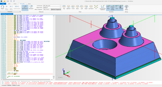
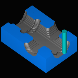
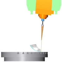
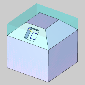
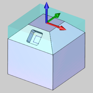
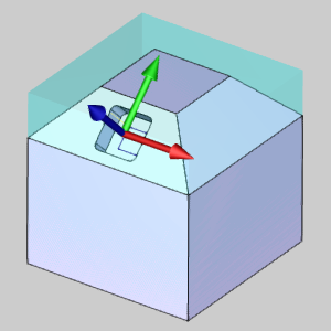
Of course, the main reason you want to upgrade to the Pro version of an editor is to be able to backplot the code to check its result on the stock. Well, you’re going to love the new simulation. From the simple things, like being able to see a gnomon with a unit indicator, being able to toggle the visibility of the axes, axes values, and the tool itself, to the big things, like being able to see the tool holder, arbor, and even your assigned coordinate systems. Simulating in an editor has never been better!
| Predator Editor |
The new NcEditor |
|
|
The NcEditor Job Setup
Using the NC Editors Job Setup UI allows for a nice graphical interface for being able to define all the information that isn't included in your NC code about the job you want to verify, like the tools, holders, work offsets, and more. In Predator you had to be familiar with their text format and add this directly into your NC program, but now with the NC Editor this is done separately and more robustly all from within the software interface! Even better, all of this done for you when you generate a program from BobCAD!
- Create new job setups to use.
- Save job setups to use later.
- Select a Machine.
- Assign a target part, and set its color.
- Assign stock geometry, and set its color.
- Use the Tool Manager section to:
- Create 12 different tool styles.
- Create Arbors.
- Create Holders.
- Create Tool Assemblies.
- Create Adapters.
- Use the Setup section to:
- Create Stock.
- Create Tool Assignments.
- Create Work, and Tool Offsets.
With all of this power, the new NcEditor will make verifying and backplotting g-code easier than ever!
General
New Language Options
BobCAM V7 now offers German and Russian language options in our software!!
BobCAM in Assemblies
There are many reasons user choose to do CAM work in assemblies. One of our few limitations has always been that our CAM system was only available while working on individual parts. We're happy to say those days are behind us. With our BobCAM for SolidWorks version 7, users can wield the power of our CAM system in parts or assemblies.
CAM Enhancements
General CAM
Advanced Feedrates
Now, in BobCAM V7 we are offering a huge amount of control over your feedrates by introducing the Advanced Feedrates page to many of the Mill and Lathe operations.
Lead-in and Lead-out Feed Control
One of the most important cuts in an operation is the initial lead-in. The feedrate used for this cut is also very important, and can sometimes differ quite a bit from the rest of the operation. In the past, there was no way to control these moves individually. You could always set plunge feedrates, and the overall feedrates, but leads would always simply inherit the overall feedrate. Finally, BobCAM offers the ability to control the feedrates for lead-ins, and the lead-outs specifically. This will be big help for jobs run on Lathes, Mills, Lasers, Plasmas, and Waterjet machines.
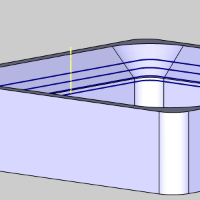
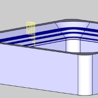
Link Feedrate Control
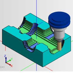
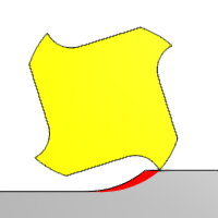
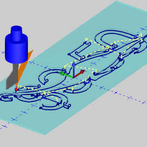
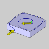
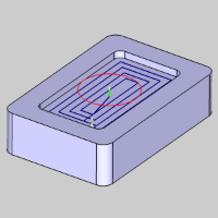
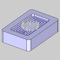
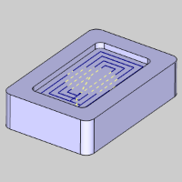
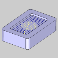
In toolpath, links occur everywhere one cut needs to connect to the next in the same region. In the image below, you can see an Advanced Z Level Finish operation, with its linking moves in yellow:
In the past, these moves have always been assigned the same speed as the overall feedrate of the operation. Now, BobCAM allows you to have control over the feedrate of these linking moves. The following operations will allow control over the link moves when the particular pattern is selected.
| Pocket
|
Advanced - Parallel
Advanced - Offset In/Out
Advanced - Morph
Advanced - Adaptive Roughing
|
| Facing
|
Adaptive |
| Advanced Rough
|
Parallel
Offset In/Out
Morph
Adaptive
|
| Advanced Z Level Finish
|
All |
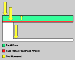
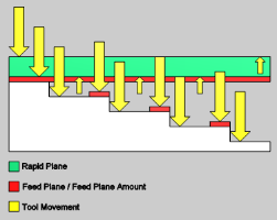
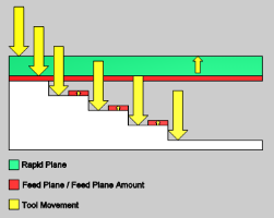
Rapid Feedrate Control
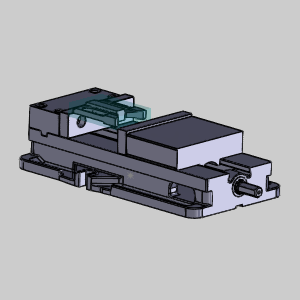
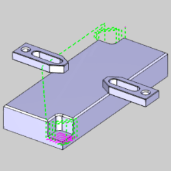
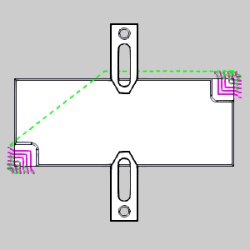
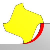
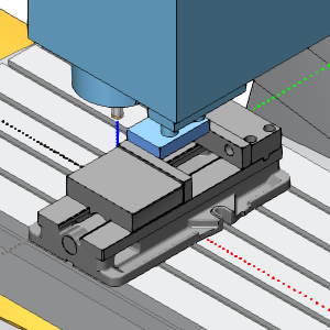
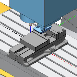
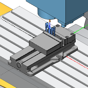
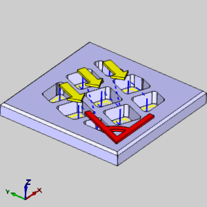
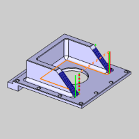
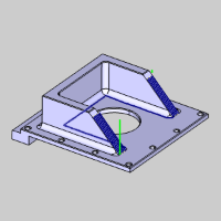
Now you can gain control over the speed at which rapids run on your machine! This can help enormously when fast moving rapids cause elbows in the rapid moves from one area to another. This is sometimes referred to as "Dog Leg Rapids", and occurs when one axis reaches its coordinate value before the other. When this occurs, what appears to be a straight rapid move in the graphics area can have an angle change in it. This isn't a big deal, until you're moving close to fixture clamps as seen in the images below:
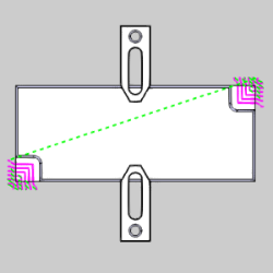
In cases like these, unexpected dog legs can cause a big problem, and will not be seen in the toolpath! The image below has been altered to show what could happen on the machine.
When this occurs, in both Mill, and Lathe jobs, being able to set a feed value to the rapids can completely correct these issues!
Adaptive Feedrate Control (Volume Based)
Another benefit of the Advanced Feedrate Control options is the Adaptive, or Volume Based, feed control. With the Adaptive feedrate control, you can set a Min, or even a Min and Max Feedrate %, so the feedrate will automatically adjust based on the volume of material being engaged by the cutter!
| Pocket
|
Advanced - Parallel
Advanced - Offset In/Out
Advanced - Morph
|
Min Feedrate % |
| Pocket
|
Advanced - Adaptive Roughing
|
Min & Max Feedrate % |
| Facing
|
Adaptive |
Min & Max Feedrate % |
| Advanced Rough
|
Parallel
Offset In/Out
Morph
|
Min Feedrate % |
| Advanced Rough
|
Adaptive
|
Min & Max Feedrate % |
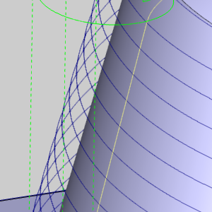
Radial Chip Thinning
Radial Chip Thinning is something many machinists are familiar with. Since most of the heat from machining is actually removed with the chips, keeping the chips at their largest possible size can be a huge help in saving tool life. In essence, the smaller your stepover, the faster your feedrate should go.
| 12% Stepover |
50% Stepover |
|
|
That's an easy thing to program when you're working with straight toolpath, but what about when working with curving toolpath? Well things can get tricky there. When using the Adaptive Roughing Pattern for Pockets, or the Advanced Rough operation, you are now able to set a minimum and maximum feedrate percentage for Radial Chip Thinning.

| Pocket
|
Advanced - Adaptive Roughing
|
Min & Max Feedrate % |
| Advanced Rough
|
Adaptive
|
Min & Max Feedrate % |
Conventional Feed Control
In the past, when using the Zig Zag method for the Adaptive Pattern on the Advanced Pocket, and the Advanced Rough operations, we would utilize the overall feedrate for both, climb, and conventional cuts. Now, users are provided with the ability to set a separate Conventional Milling Feedrate.
Edit Operations from the CAM Tree
In the CAM Tree, right click on a particular operation and click Edit. Now, when the wizard launches, it will open on the tool page for that exact operation.
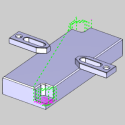
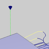
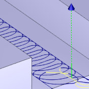
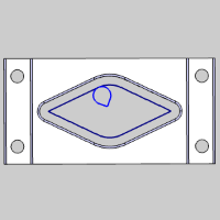
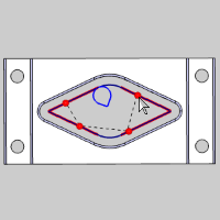
Start and End Indicators
In many cases, once toolpath has been created, the users first concern is where the operation is starting and ending. Having to wait for the simulation to launch just to verify that was never fun, and when we created the Backplot options to view tool movement directly in the graphics area, it was a huge help with this. In this version however, we've gone a step further and created the Start and End Indicators. Just click on an operation, and along with the toolpath highlighting in the graphics area, the Start and End Indicators will now show where the toolpath starts and ends.
Update All Geometry
In the previous
version of BobCAM we provided a way to Update All Geometry in your
CAM Tree for times when, for whatever reason, something about the geometry
associated with your features changed. It was a hit! For this release,
we took it a step further. Start Point locations and Chain directions
for your Mill 2 Axis features are saved. Now, no matter how many features
you took the time to customize the Start Point and Chain Direction for,
they can all be updated, and all your customizations will be retained,
even if you modify the machining origin location!
Lock and Unlock Operation in the CAM Tree
Features and Operations can now be locked in order to keep them from
being computed. This is extremely helpful when editing toolpath. Once
an operation has had toolpath edited with the Edit Toolpath dialog, the
operation will have an  icon in front of it, and the name of the operation will appear in red
font. This helps to ensure that the edits to the operation are not accidentally
lost due to recomputing the operation by mistake.
icon in front of it, and the name of the operation will appear in red
font. This helps to ensure that the edits to the operation are not accidentally
lost due to recomputing the operation by mistake.
Mill
Mill Express
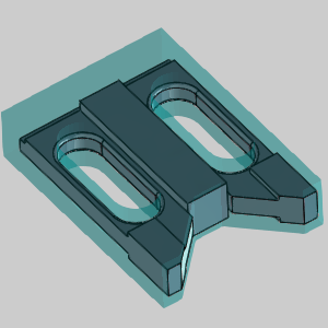
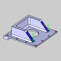
Fixtures
One of the main reasons to do CAM work in an assembly is to view the fixtures being used for the various machine setups, and to be able to check them for collisions. Now that BobCAM is able to operate inside of assembly files, assigning fixtures to each machine setup is as easy as "1, 2, 3." Simply right-click the fixture item under the associated machine setup, and select Re/Select, then pick the fixture geometry as it appears in the proper configuration, and select OK. This can be repeated for as many machine setups as necessary. Now, when you simulate, you will be able to see the selected fixture geometry, in the configuration it was selected in, for each setup!
| Machine Setup - 1
|
Machine Setup - 2
|
Machine Setup - 3
|
|
|
|
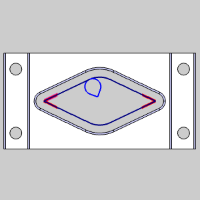
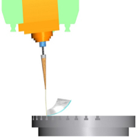
Drag Knife
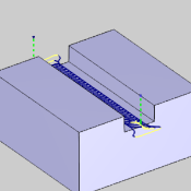
A brand new type of feature is now available in the BobCAM V7 release: The Drag Knife feature! Drag Knives are used in the inlaid veneer industry, the artwork industry, and by everyday hobbyists to cut things like snowboard and ski base materials, wood veneer for inlay/marquetry artwork, leather, carbon fiber pre-preg laminates for aerospace, military, and automotive components, cardboard for custom packaging, and much more. Whether you want to perform delicate veneer inlay work or cut out cardboard boxes with your CNC router, the Drag Knife feature is the right feature for the job.
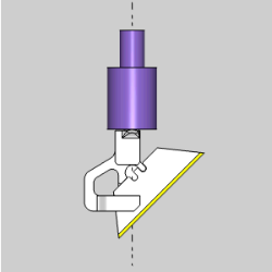
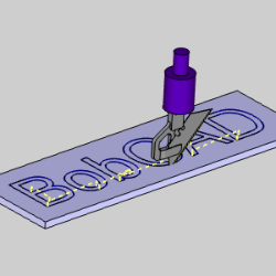
The Drag Knife also supports the Backplot function, which allows you to view the tool motion directly in the graphics area!
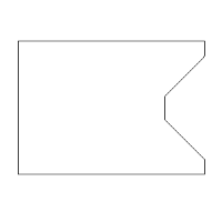
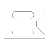
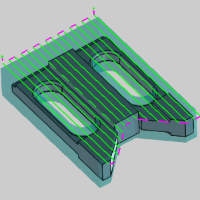
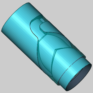
Mill Facing Feature
BobCAM now introduces another brand new feature: The Mill Facing feature! While we've always offered a Facing operation, it was accessed by creating a basic 2 Axis Feature. The only issue with this was that 2 Axis Features require geometry selection, and CAD models rarely contain geometry specifying the required stock shape. This meant the user now had to take the time to create that geometry. With the new Mill Facing feature, geometry selection isn't even necessary. Not only that, but if you select a Workpiece for the job, the new Mill Facing feature even sets the depth automatically, and gives you options on how to deal with the geometry! Choose from the default shape, a bounding box, or Keep Internal Loops.
| Part and Stock |
|
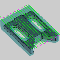
| Default |
 Bounding Box Bounding Box |
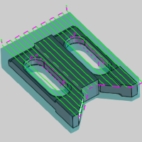
Keep Internal Loops |
| Feature Preview |
Feature Preview |
Feature Preview |
|

|
|
| Result |
Result |
Result |
|
|
|
Adaptive Pattern
For this release we have added a new Pattern to the Facing operation.
Besides the basic Zig and Zig Zag Patterns, you can now choose the new
Adaptive Pattern when using the Facing operation. This will allow you
to apply a high speed style toolpath that is both fast, and highly effective.
New Machine Sequence Options
BobCAM now offers new and improved sequencing options in order to offer lower cycle times. Two new, highly effective ways to maximize the efficiency of the sequence are now available. Along with our standard No Sorting, X/Y directions, and Closest options, a Custom Direction option you can define yourself has been added. We now even offer an Optimized sequence! With the Optimized option, each sequence is tested along with its own algorithm and the result which creates the shortest toolpath is the one you get!
| Custom Direction
|
Optimized
|
|
|
Multiple Step Chamfer
The Chamfer operation now gives you the ability to use multiple depths!
Selecting the Multiple Depths option allows you to set the Depth of Cut,
gives you an option to use a Stepover, gives you control over the order
of each of those, and even provides you the option to utilize the Minimize
Retracts feature.
|
Single Depth
|
Multiple
Depths
|
with Stepover
|
|
|
|
|
Pecking Entry Option
Operations that offer a Plunge entry method will now offer three different
Types of Plunge: Single Depth,
Peck, and Fast Peck. These options can be a huge help in saving time and
tool life!
|
Single Depth
|
Peck
|
Fast Peck
|
|
|
|
|
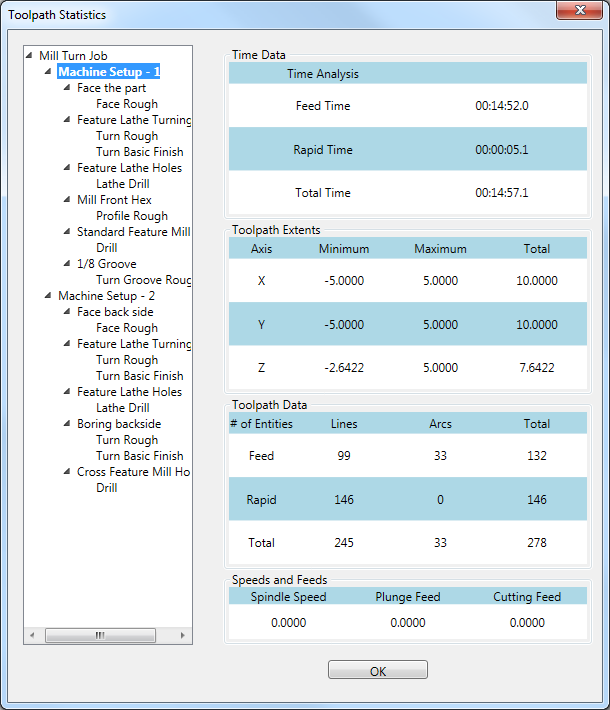
Toolpath Statistics Dialog
The Toolpath Statistics dialog is now available to give you some useful
data about the current toolpath of an existing job. The Toolpath Statistic
dialog will give you even more information than can be found in the Setup Sheet.
While the Setup Sheets provide information like the speeds and feeds of
a tool, the Toolpath Statistics provide additional information, like Feed
Time, vs Rapid Time, the extents of the toolpath, and even the amount
of toolpath entities; Feed entities vs. Rapid entities.
Extension
Every now and
then, the situation arises that calls for the feature geometry to be adjusted.
Perhaps during simulation you notice a move that is a little too close
or one that could probably be cut back a little bit to save time. In either
situation the result would be the same: Time to adjust the model with
CAD tools. Now, new Extension options will allow you to extend and trim
the virtual feature geometry without the need to adjust the actual CAD
geometry!! Choose the Start / End option, and then enter the values to trim
and extend those virtual geometries along the chain. This can all be done
without the need to touch a CAD tool!
|
Extension Off
|
Extension On
|
|
|
|
Mill 3 Axis Standard
Edit Toolpath
Here, at BobCAD-CAM, we are proud to provide our customers with
the best in cutting edge technology (pun intended). However, even when
using the best toolpath strategies on the market, you may occasionally
create a cutting operation that's perfect, except for one little thing.
These situations can be frustrating, since it can be difficult to make
the change you want, without affecting the rest of the toolpath you are
so happy with. BobCAM now puts the power in your hands to change anything
you want, about any portion, however small, of an operations toolpath
with our Edit Toolpath dialog. The Edit Toolpath dialog gives you the
ability to:
Delete
Allows
you to delete toolpath entities and relink the toolpath.
Trim
and Relink
Allows you to create a trimming boundary
to trim portions of the toolpath away.
Move
Allows you to move toolpath entities and link to their newly located position.
Replace
Allows you to draw in your own toolpath
and replace entities of the toolpath with this CAD geometry.
Convert
to CAD
Although it is not a command, the Convert to CAD button is listed here
as it is extremely helpful when using the Replace command. The Convert
to CAD button allows you to select regular toolpath and turn it into CAD
geometry. This allows you to create a connection point when adding additional
geometry, or it can even be used to turn the toolpath into geometry, in order to then modify that geometry and turn back into toolpath!!
Break
Allows you to split toolpath entities
into multiple segments. This could be used, for example, to later modify
a segment of that toolpath, to change the feedrate of a segment, to delete a segment, or many other uses.
Modify
Attributes
Allows you to modify the feedrate,
or feed type.
Extend
Cut Move
Allows you to extend the toolpath tangentially
by a specified distance.
Edit
Tool Axis
Gives you the option to modify the
tool orientation vector for a selected set of toolpath entities.
New Pocketing Patterns
In the New BobCAM V7, we offer two main pocketing pattern types; Standard Pocket & Advanced Pocket.
 Standard Pocket
 Advanced Pocket Advanced Pocket
Parallel Offset Pocket Out Offset Pocket In
|
Standard Pocket Advanced Pocket Parallel Offset Pocket Out Offset Pocket In
|
| |
Morph Spiral
Adaptive Roughing
|
While the Standard Pocket type still uses the same basic patterns, the Zig Zag pattern is now called Parallel. In the Advanced Pocket, we offer two brand new patterns: Offset Pocket In, and Morph Spiral.
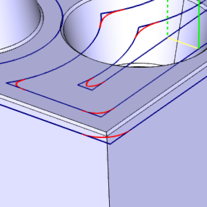
Advanced Offset Pocket In
In order to put another tool in your toolpath arsenal, we are providing you with, yet another method of cutting a pocket. When using the Advanced Pocket with an Offset Pocket In, rather than the standard method of starting from the outside, and working your way in, this toolpath starts on the second row, so when the tool is cutting in full engagement it stays well away from the finished wall. The toolpath then works its way in, and finally comes back to tackle the first row, leaving much cleaner material behind.
Morph Spiral cutting for Pocket
A new pattern option has been created for the 2 Axis Advanced Pocket. By popular demand, the Morph spiral has been created to maximize the efficiency of the offset pocket. By morphing the offset shape into a spiral we help eliminate the slowdowns of those pesky linking motions.
Smooth Connections for Parallel roughing
When cutting 2 axis pockets with the Zig Zag pattern, the only option to link passes has been a direct route. This is not always ideal, since hard angle changes always cause a lot of slowdown. To stop moving in one direction, you need to slow down, to begin moving in another direction, you have to start from a stop. In BobCAM V7, the Zig Zag pattern, which is now called Parallel, offers a new parameter, called Smooth Connections. Smooth Connections allows you to eliminate the hard angles between passes, and replace them with a radius value to keep the tool moving and avoid the slowdown of those hard angle changes.
Breakthrough overlap for Adaptive Roughing
When creating an open pocket using the adaptive roughing method, we would sometimes find ourselves in situations where the toolpath didn't quite remove enough material from the opening before coming back with cleanup passes to remove the left over amount. This was easy enough to correct, but it did require the creation of new geometry to select for the feature so you could force it into doing what you wanted. An easy fix, but not easy enough. Now, we've added a simple slider control in the Parameters page called Break through amount. This allows you to set the slider to either Less, or More, which will set how much material will be left for the cleanup passes to handle.
Mill 3 Axis Pro
Advanced Rough
We have introduced the two new cutting patterns to the Advanced Rough as well. While the Advanced Rough has had the Offset, which is now called Offset Out, Parallel, and Adaptive Roughing patterns, the available patterns are now:
- Offset Out
- Offset In
- Morph Spiral
- Parallel
- Adaptive Roughing
Advanced Rough Offset In Cut Pattern
In order to put another tool in your toolpath arsenal, we are providing you with, yet another method of clearing an area. When using the 3 axis Advanced Rough with a Offset Pocket In, rather than the standard method of starting from the outside, and working your way in, this toolpath starts on the second row, so when the tool is cutting in full engagement it stays well away from the finished wall. The toolpath then works its way in, and then comes back to tackle the first row, leaving much cleaner material behind.
Morph Spiral Cutting Pattern
A new pattern option has been created for the 3 axis Advanced Rough. By popular demand, the Morph spiral has been created to maximize the efficiency of the cuts. By morphing the offset shape into a spiral we help eliminate the slowdowns of those pesky linking motions.
Smooth Connections for Parallel Cut Pattern
When cutting with the Parallel pattern, the only option to link passes has been a direct route. This is not always ideal, since hard angle changes always cause a lot of slowdown. To stop moving in one direction, you need to slow down, to begin moving in another direction, you have to start from a stop. In BobCAM V7, the Parallel pattern offers a new parameter, called Smooth Connections. Smooth Connections allows you to eliminate the hard angles between passes, and replace them with a radius value to keep the tool moving and avoid the slowdown of those hard angle changes.
Dynamic Holder Collision Avoidance
This is a new option in the Gouge Check page of the Advanced Rough operation.
Unlike other gouge checking options which check for gouges once the toolpath
has been calculated, and then
trim and relink, this option checks for gouges during the toolpath calculation.
You can now check holder with: In Process Stock, or Machining Surface.
In Process Stock constantly updates what stock would be remaining as it
is removed by the tool. This is extremely helpful, since, as the stock
is removed, it is no longer a concern for collision. The Machining Surface
option is most helpful when the model extends beyond the stock.
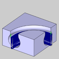
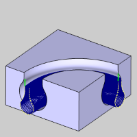
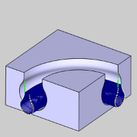
Arc Leads for Adaptive Roughing
To
help create smooth entry and exit options, the adaptive roughing option
now offers a Vertical Arc lead when using the plunge entry method for
the Adaptive Roughing pattern. This option enables you to utilize vertical
tangential arc moves as default lead-in/out segments instead of linear
leads.

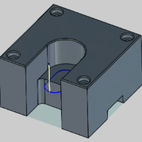
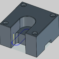
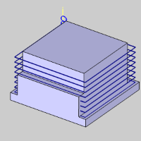
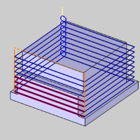
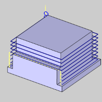
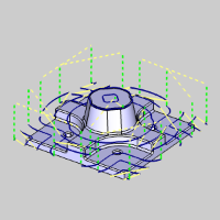
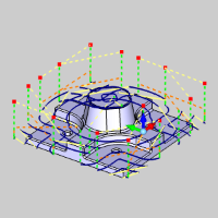
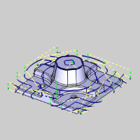
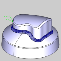
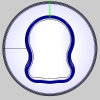
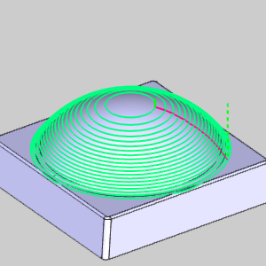
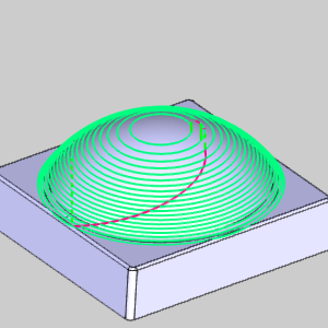
Advanced Z Level Finish
Start Point Control
With all the power available in the Advanced Z Level Finish, there was one area it was lacking in; the toolpath calculation determined the start point. When programming a part, the more control you have, the better. That's why in V7, we now offer control over exactly where your Advanced Z Level starts! The Start point can be selected from the graphics area, or it can even be entered manually.
| Undesirable Start Location |
Adjusted Start Location |
|

|
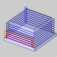
This works for the regions as well! Whereas the above example has only one start point, operations with multiple regions have multiple start points as in the examples below. Notice the original part with toolpath, and notice the start points being affected with the selected start points.
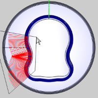
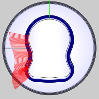
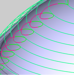
New Linking Options
Along with the control to set the start point of the Advanced Z Level Finish, we are also providing brand new methods of linking one pass to subsequent passes. Along with the links that have been available for the Advanced Z Level Finish, you can now also use Horizontal/Vertical, and Spiral.
| Horizontal / Vertical |
Spiral |
|
|
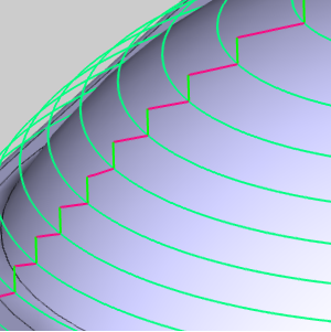
Shift Subsequent Passes
Normally, no matter which linking option is selected for the Advanced Z Level Finish, the start of the next pass is basically straight down from the end of the previous pass. This isn't always an issue for most, but in some cases, the best practice is to move the start point of the next pass, so an obvious line isn't visible in the final product. In our latest release, you can do just that. By selecting the Linking Position option, you can enter a value, and the start of the next pass will be offset by that amount. This is a great way to "blur the edges", and get the best finish possible.
| Default |
Shift subsequent passes by: |
|
|
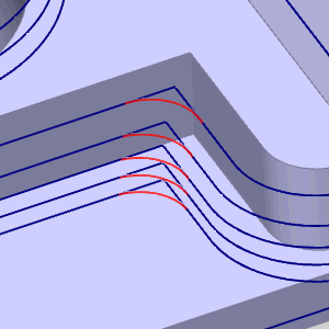
Undercuts for Advanced Z Level Finish
The Advanced Z Level Finish now offers the ability to machine undercuts!
In the past, although lollipops and t-cutter style tools could be used,
the toolpath created would not accommodate undercut areas of the model.
Now, you can, not only, cut undercut areas of the model, but even specify
to cut only the undercut areas
of the model!
|
 Undercuts Undercuts
|
 Undercuts Undercuts
|
Machine only undercuts
|
|
|
|
|
Improved Round Corners / Smooth Corners Calculation
Not only do we create brand new tools and features for our releases, but we are also constantly working to make what we have better, for us, and our customers. In this version, one of those improvements is to the calculation of our Round Corners option found in the Advanced Z Level Finish, along with the Advanced Planar, and the Smooth Corners option found in the Advanced Rough. This greatly enhances the ability to run higher feedrates when using these toolpaths for roughing and semi-finishing operations.
Expand the Rest Machining Area
Since the introduction of Rest Machining in BobCAM, users have been making the most of it. Being able to create an operation which only focuses on the areas left by a larger tool on a previous operation has certainly proven invaluable! The only thing we noticed along the way, however, is it can be a little too exact. In machining, having a little overlap is usually the way to go to keep things as clean as possible. That's why, in BobCAM V7, we are introducing the Expand Rest Area option. This provides the ability to extend the area that will be rest machined in order to provide enough overlap to have it machined well.
The Expand Rest Area options are now available in the following operations:
- Advanced Planar
- Advanced Z Level Finish
- Project Curves
- Equidistant
Mill 3 Axis Premium
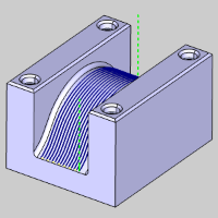
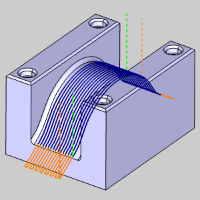
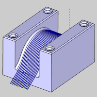
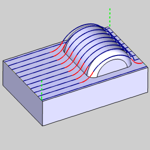
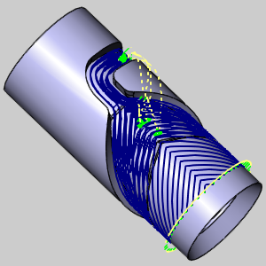
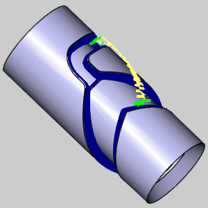
Multiple Surfaces for Flowline
When we introduced the Flowline toolpaths, it changed the way we created toolpaths. Clicking one surface and having the software do the work was a lot easier than selecting several different pieces of geometry to help define the toolpath. However, the only problem with the flowline toolpath was that it only worked for one surface at a time. Needing to apply toolpath to one single surface is definitely the exception and not the rule. Normally toolpath needs to cover several different surfaces. With the new flowline options, you can select multiple surfaces at once. Although the surfaces are technically still calculated individually, the toolpaths are then linked together to create one continuous operation.
Lead In – Reverse orthogonal line
The Reverse Orthogonal Line has now been introduced to offer the ability to change the direction of the orthogonal line lead when needed.
Automatic Arc lead
Toolpath cutting moves, and retract moves can sometimes feel at odds with each other. In an effort to create smoother overall toolpath, the Automatic Arc Lead offers a way to blend out of the cut move, and into the linking move with a tangential arc. The Automatic Arc consists of two splines. The first spline leaves the surface tangentially in the surface normal direction of the relinking. The second spline connects tangentially into the plunge or retract motion using the tool axis tilting orientation.
Mill 4 Axis Standard
4 Axis Rotary: Adaptive Stepover for the Around Cut Style
When using an Around Style cut, users now have an option to apply an
Adaptive Stepover. This is the same functionality that was a huge help
in other 3 Axis toolpaths. With the Adaptive Stepover, steep areas that
would normally cause gaps in the toolpath are filled with additional passes
to match the consistency of the rest of the toolpath. What would usually
require an additional operation to finish, can now be done all in one
operation.
Mill 4 Axis Pro
4 Axis Advanced Rough and 4 Axis Advanced Finish Operations
Users familiar with our 4 Axis toolpaths can tell you, getting the perfect 4 Axis toolpath on complex parts could take a little work. Geometry selection needed to be precise. You would need to specify each surface to cut, you would need some edges to help define the pattern it should use, and because you were selecting individual surfaces, some gouge checking against particular surfaces might come into play. Finishing may need a couple different operations to achieve the desired result. Now, for the first time ever, you can pick the entire model and get the results you need, in a fraction of the time. The new 4 Axis Advanced Rough, automatically recognizes where the stock is, and avoids air cuts. The Advanced Finish automatically recognizes the walls in need of finishing, and tackles them precisely.
| Specified Stock
|
4 Axis Advanced Rough
|
4 Axis Advanced Finish
|
|
|
|
Notice in the images above, the roughing toolpath ends where the stock ends, and the finish focuses only on the walls of the part model. Getting excellent 4 Axis results like these has never been easier!
Rapid Distance in Tool Plane
The rapid distance, including the
feed distance, can be applied in the tool plane instead of the tool
axis plane. This option can be used for machining with undercut tools,
e.g. a slot mill, where the engagement is usually from the side and axial
retractions are not wanted.
Tool Axis Smoothing
When tools move through a valley of surfaces, the valley can cause to tool to make wide changes in angle when attempting to cut normal to the surfaces. In order to allow a smoother transition between these areas, the Smoothing options have been added to the Tool axis control page.
Mill 5 Axis Pro
Contact Point Based Feed Rate Optimization
This functionality finds its application
in grinding processes and not in classic milling operations. To achieve
a constant feed per tooth, the toolpath feedrate is controlled by the
actual contact point of the surface and the contact point of the tool.
Swarf
Normal to Guide Curve
The tool axis is oriented normal to the guide curve.
Swarf Sorting - Start From Bottom
To give you the control you need,
the sorting algorithm for multiple cuts has been extended. For best material
removal performance, the first cut can now start from the bottom. You're
welcome.
Multiaxis Roughing
Dynamic Holder Collision checking against stock
This is a new option in the Gouge Check page of the Multiaxis Rough operation. In our BobCAD-CAM V30 release, we presented this option for our 3 Axis Pro module. Now, in BobCAM V7 it is available for the Multiaxis Roughing toolpath. Unlike other gouge checking options which check for gouges once the toolpath has been calculated, and then trim and relink, this option checks for gouges during the toolpath calculation. You can now check holder with: In Process Stock, or Machining Surface. In Process Stock constantly updates what stock would be remaining as it is removed by the tool. This is extremely helpful, since, as the stock is removed, it is no longer a concern for collision. The Machining Surface option is most helpful when the model extends beyond the stock.
Extend cuts for stock
When using the Morph between ceiling and floor strategy of the Multiaxis Roughing, you can now choose to extend the toolpath beyond the selected ceiling surface with the Extend cuts for stock option. This can be found in the Advanced section of the Roughing page. This option can be used to extend the morph toolpath to the top of the stock material when it is located above the ceiling surfaces.
Gradual Front Shift Change
This feature is for shifting the
tool contact point as it moves along the contour. This can be used for
a polishing process, where in the beginning of the machining process the
tool sits on the front, and at the ends it runs on the heel.
|
On
|
Off
|
|
|
|
Enhanced Multiaxis Roughing
The new algorithm
in the Multiaxis Roughing now supports rotational, or so called periodic
pocket geometries. This was considered a major limitation to multiaxis
machining even though the initial design was never supposed to support
it. The tool does not continuously follow the pocket, but an overlap is
guaranteed when the pattern returns on the surface edge seam. As seen
in the image below, the new algorithm helps to ensure that all areas are
handled with smooth multiaxis movements.
Gradual side tilt angle change for fixed angle to axis
This
new feature gives an incredible amount of control over the range of tilt
during machining. While there are many options when it comes to setting
the tilt of the tool, there has never been an option quite like this one.
Just define the start angle and the end angle, and the tool gradually
changes the tilt angle between those angles. This is extremely helpful
in cases similar to a turbine blade finishing toolpath, and can help to
ensure that the tool stays clear of obstacles like the blade root.
Linking - Clearance - Blended Spline
This feature enables two contours
to be linked with a new blend spline and is available for Gaps along cut,
and Links between Slices and Passes. This option enables a smooth transition
between contours and In the event of a detected collision, the blend spline
is extended to ensure the main shape is not disturbed and to guarantee
a smooth transition.
Automatic Arc
The new Automatic Arc lead option
is a great way to ensure nice, clean leads. The automatic arc consists
of two splines. The first spline leaves the surface tangentially in the
surface normal direction, similar to a tangential arc. The second spline
connects tangentially into the plunge or retract motion, using the tool
axis tilting orientation. This lead option even works in combination with
collision checking.
Automatic Start Height for the Position Line Lead-in
When using
the Position Line lead option, the start/end position of a cut is defined
by a line. The line defines the direction of the tool axis as well as
the height of the tool. Because this line is absolute, all following retractions
will go to same position and height. A new option has been added to this
lead called Automatic start height. Using this option means the height
along the line is not absolute, but is automatically adjusted to the cut
position.
|
Automatic
Start Height On
|
Automatic
Start Height Off
|
|
|
|
|
|
|
Automatic Clearance Area
Taking us another step closer to
one-click machining, is the new Automatic Clearance Area. While, most
will want to have control over the exact clearance area types, and distances
being used, with this new feature the system automatically determines
the clearance area type, position, and dimension. Using this method, it tries to maintain
the most suitable setting for each pattern. It doesn't get any easier
than that.
Mill Turn
Chuck Jaws
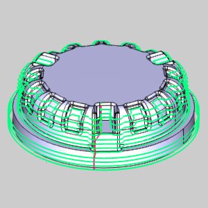
For the first time ever, BobCAM offers a simple solution to quickly define chuck jaws in the user interface and view them in the simulation. Now, you can easily check chuck jaws for collisions, verify jaws opening and closing, spinning, and even syncing properly for part transfers!
Posting Enhancements
New Multiaxis Posting
New Multiaxis Posting options are available when using Select Between
The Two Solutions. When moving the material and tool into position, there
are instances where two solutions exist which achieve the same result, and in
the past, you could choose between them with the options First Solution
and Other Solution. The only problem with this, was that it could be frustrating
in cases where you have a particular outcome in mind. In those instances,
if the first solution wasn't what you were looking for, you would need
to go back and choose Other Solution. Now, other options exist that give
predictable results: Solution closest
to 0 and Solution not closest
to 0. With these options, the sum of the 2 angles has been
found for each solution. This way, when you select Solution closest to
0, you know which result you are choosing.
|
Solution
closest to 0
|
Solution
not closest to 0
|
|
|
|
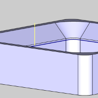
Each controller may use a different name for it, but whether your controller refers to it as Tilted Work Planes, Transform Planes, Slope Machining, or anything else, what it actually does is shift the work coordinate system to make things possible which, otherwise, would not be. For instance, drilling canned cycles cannot be output if the tool is not aligned with the Z axis of the coordinate system. By using a Transform Plane, we can shift the coordinate system to make this possible. When an operation is being done on an indexing system, most controllers aren't able to use machine compensation. By tilting the coordinate system, the controller is able to tell exactly where to put the tool to compensate properly. In many cases, machinists need to make adjustments to jobs on the fly, but on each and every job, it is always good to be able to look at the code and know exactly what to expect. However, this can get pretty tricky when working with jobs that aren't completely flat. Simple coordinates can get pretty tricky! Look at the part below; a simple profile, when done on an index system can have pretty confusing X, Y, and Z coordinates called:
| Simple Profile |
Coordinate System |
|
|
| Output without Transform Plane |
|
N13G01 G93Y-0.4697Z-0.3536 F3.3369
N14Y-0.6464Z-0.5303 F6.6738
N15X0.1250
N16Y-0.4697Z-0.3536
N17X-0.1250
N18G00Y-0.7879Z-0.0354
N19Y-1.1187Z0.2955
|
Now, let's take a look at how easily that code can be read, and even updated, if we use a transform plane.
| Simple Profile |
Coordinate System |
|
|
|
| Output using the Transform Plane |
|
N13G68.2X0.0000Y-0.7.4800Z-0.2652 I00. J45. K00.
N14G53.1
N15Y-0.1250
N16Z0.2000
N17Z0.1000
N18G93G01Z-0.2500 F3.3369
N19Y-0.1250 F6.6738
N20X0.1250
N21Y0.1250
N22X-0.1250
N23G00Z0.2000
|
Origin Tracking
The Move List Writer, of the Multiaxis Posting page, has had its Move List Coordinates group upgraded. The Move List Coordinates now offer the ability to have different settings for Standard, Indexing / Positioning, and Multiaxis Simultaneous Motion outputs. Along with the available settings, in BobCAM V7, we now offer Origin Tracking!
| G43
|
TCP
|
Origin Tracking DWO
|
|
|
|
Post Processor Encryption
We now offer customers the ability to encrypt particular portions of
a post processor, or even entire post processors to hide data within the
post from the general public. This is accomplished in three easy steps:
pick your post, pick a name for it, and pick who can use it. The encrypted
posts can be set to work with any License ID, particular License ID's,
particular Customer ID's, or a combination of particular License, and
Customer ID's. Post encryption will be most useful with post containing
custom scripted functionality. A BobCAD dealer, or partner may want to
encrypt a post they have written for a particular customer. A shop owner
may want to encrypt a post that gives his machine custom functionality
so an employee won't be able to give it to his buddy in the shop down
the street with the same machine. Either way, everyone now has the ability
to make their post proprietary if they so choose.
Example of a Post with a portion encrypted
|
262. Add sign to all coordinate values? n
267. Amount to add to tool # for tool register value?
<--ENCRYPTED BEGIN
// The post will work on ANY license ID
XRY6MWZE8Q6ERUQH2YJ6R7TNZNC5
HEDGCY2IVQWFETMY42DCDBJYSN90
7SFTPRAQ2IYQ82E8V5ZRFIFHQI79
JMTZJMZU3ZR26JQEV74Y76DGBBWTJXXR2FKDEXRRAZSPTDNVV93S64
RQYY4CYUHGISSPDYN55RYP5WIWEB
ET24SPQNZ6GJ3U2YKBJVSNBHTGJCAAC6VTG9FE72FT9EHH6XPKSAC1
<--ENCRYPTED END
273. Output programmable rotary axis codes? y
280. Primary Rotary Axis Modal? y
|
Posting Question 447. When using DPM, Polar should be output as UPM? y/n
In order to support all possible cases, this posting question has been added to allow users outputting in degrees per minute, the option to output units per minute during polar interpolation moves.
New Posting Variables
Just as we have added a new posting question to support all possible cases, we have also added a few new posting variables that can be used in Mill and MillTurn output:
- xf_no_output - Updates modality with the new X position but does not output the position to the NC file.
- yf_no_output - Updates modality with the new Y position but does not output the position to the NC file.
- zf_no_output - Updates modality with the new Z position but does not output the position to the NC file.
Simulation Enhancements
Split Simulation into multiple views
Usually, when simulating, users have a couple of different areas of the part they would like to focus on during the simulation. Whether it's to check the tool angle against the material, or to make sure tool movements between cuts are as close as possible, while still being safe, the result is the same; watching the simulation over and over, from different angles, to make sure everything is the way you want it. This can be a little frustrating when you finally rotate the view into the perfect angle, then need to check another view, only to have to try to get back to that same view again later. Now, this can be done with ease! In the View ribbon, click the down arrow under Viewports and choose between  4 views,
  3 views,
  2 rows, or
  2 columns. Now several views can be covered at once, and those difficult to get to views, can be left alone while other views are adjusted.
When simulating your part, trying to find information on a certain area of toolpath can be frustrating. It usually requires adjusting the speed bar, pressing play, trying to stop soon enough, and then slowly stepping through the toolpath move by move until you finally get to the area your looking for. Don't worry, those days are behind you now. Today, in BobCAM V7, all you need to do is double-click on the toolpath segment in question to have that exact move called up in the move list.
Opaque
In the Machine Definition page of the Current Settings dialog, you can define how components are shown in the simulation. The adjustable attributes of the components include a transparency setting, which defines how visible the component is when it's set to Show in the graphics area. In the past, the only other options for component visibility were, Transparent, and Hide. This meant if a component was given a transparent attribute in the machine definition, you were not able to see that component as opaque in the simulation. Now, an Opaque option has been created to allow components defined as transparent to be shown opaque without the need to redefine it in the current settings.
Layer Interval
In many cases toolpath can be a little overwhelming to look at. With so much going on, it can be difficult to zero in on an area of interest. Now, in the Toolpath Rendering group, of the Simulation ribbon, you'll find Layer Interval, and the Layer Interval Settings. This option allows you to specify a height range and location. With that specified, any toolpath outside of that defined range will be hidden. This is a great way to cut through confusing rapid moves, to get to the meat of the toolpath, or even analyze each Z level of the toolpath!
A/B/C Axis Value Change
You can now set the simulation to show changes in the A, B, or C axis by changing the color of the toolpath. In the Analysis tab of the simulation, select from:
- A Axis Value Change
- B Axis Value Change
- C Axis Value Change
With the axis of interest selected, you can set the range for colors and the associated value change they represent, or allow the system to auto adjust the settings. With the settings applied, the toolpath will show a change in color as the particular axis changes in value.
Operation Highlight
In the simulation, you can change the colors for each and every operation being applied in the simulation. This can be handy, but depending on the number of operations, it can be a little overwhelming. In this version, another option has been created in the  Analysis tab of the simulation. Now, we've added the Operation Highlight option, which allows you to simplify the colors down to one for the Current Operation, and a second for Other Operations. This way, instead of having a separate color for each and every operation, the color scheme is simplified to what is being done now, and what is not.
Thicken Operation
For several versions now, BobCAM has given users the ability to click on an operation in the CAM Tree to make the toolpath associated with that operation turn bold in the graphics area. This helps the toolpath of the current operation to stand out visually. It was a small feature that was actually a huge help! Now, in the Toolpath Rendering section of the simulation, the same thing is available. Users can now select the new Thicken Op option to make the toolpath of the current operation bold.
Scrolling through the  Move List has always been helpful, but in this version of BobCAM, it can do more than ever before. Right-click in the Move List, select Settings, and, In the Move list settings dialog, select the check box for Show text colors based on Toolpath Analysis option, and press OK. Now, when the Move List is viewed, the font color of the listed values will update based on the corresponding settings in the Analysis tab. This can be set to update the color for everything from a Height Change, to a Tool Number change. Now you'll be able to see all these changes, without ever taking your eyes of the Move List values.
The Move List now allows users to right-click on the moves and choose either Jump to First Move, or Jump to Last Move to quickly find the moves in question.
Ruler
The ruler shown in the bottom corner of the simulation now has a vertical
aspect to show height. In the past, the on screen ruler only displayed
the width. This has been updated to give you a better understanding of
size without the need to enter the measurement functions.
Measure Grid
In the last several versions, the simulation has been offering more and more for quick measurement references. First, a horizontal ruler was offered in the corner of the screen. Now, along with vertical ruler been added, you can even go to the View ribbon, and select the  Measure Grid icon to overlay the entire screen with a measurement grid. Click a second time to turn it off.
Zoom Window
To help users analyze the model and stock easier, we now offer a Zoom Window option in the simulation window. In the right-click menu, you can select Zoom Window to allow you to click twice in the graphics area to create a rectangle to zoom to.
Show Previous View
Finding the perfect view to see what you want to see in the simulation, can sometimes be tricky. When you have a hard time getting to the perfect view, and then accidentally alter that view, it can be pretty frustrating. Now, with the Show Previous View option, this is no longer an issue. Choose from several different previous views using the right-click context menu, or simply use Ctrl+Z while in the graphics area of the simulation to easily move through the most recently used views.
Full Screen Mode
In any application, space is always at a premium. In the past, users would sometime settle on a smaller view window than they would actually want, because it was easier than having to resize the information tabs in the simulation just to gain an inch of viewing area in the simulation. Now, its quick and easy to go full screen. Either press F11, or select Full Screen Mode from the right-click context menu to quickly push the simulation window to its maximum viewing size. This allows you to take over the space of the entire ribbon, and the space in all the information tabs easily. Once you are done with full screen, simply press F11, or select Full Screen Mode from the right-click context menu to go right back to the previous size, without the need to manually resize anything.
This new feature, for automatic coloring of the Tool Axis Vectors and Tool Path Points, will now draw these graphics elements with colors very similar to the toolpath line color. This function will work best with a toolpath analysis option like Tool Number or Operation Number.
Display Arrows Show Axis Direction
This new option is the easiest way
yet to get familiar with a machine and its axes. In the past, when getting
familiar with a machine, the best way to test machine components in the
graphics area was to go into the axis control pane, and start clicking
on the sliders for each axis to move it up and down. This would, in turn,
move the associated machine component in the graphics area. Now, you can
simply go into the machine pane and click on an axis. The associated machine
component will then highlight in the graphics area, and will even display
an arrow showing positive direction and rotation when applicable. This
helps end guess work and gives you a ton of data at a simple glance.
Highlighting an Object in Simulation
In previous versions, you could click
on an item in the Machine tree to have the object highlight in the graphics
area. This could be useful if you wanted to know what axis a particular
object in the graphics area was linked to. The drawback, however, was
you would need to go through the machine tree clicking items until the
object of interest highlighted in the graphics area. Now you can hold
Ctrl and double right-click directly on an object in the graphics area
and the associated item will highlight in the machine tree.
Highlighting for the Collision Checking Group
The simulation should be as informative
as possible at simple glance. In order to assist in this, the objects
in the viewing area are color coded for each Collision Checking group
and grey for non-selected objects. Just click on the Collision Check group
in the machine list and the objects in the graphics area will highlight
to show you what is being checked against what.
Machine Simulator Move List improvements
The Move List pane now has the ability to adjust the order of the columns,
resize the columns, and even has a handy new addition called the Field
Chooser. Right-click anywhere in the pane and select Field Chooser and
you can drag and drop additional columns to and from the field chooser
with ease! Now you have control over the look and content of the Move
List.
Axis Control
The Axis Control pane has been updated to give you the ability to set
the axis to a particular value directly in the pane. In the past, if you
wanted to set an axis to a particular location, you had to right click
on the slider to launch the Set Axis Values dialog box. The axes could
then be adjusted to a particular location, but that value had to be entered
in specifically, and the result could not be seen until you exited the
dialog. Now, these adjustments can be made without launching a separate
dialog, and a stepper has been added for those instances when the exact
location is not known. Simply use the slider to get close and the stepper
to hone in on the exact figure.
All pop-up notifications have been
improved and now have different options for disabling their display during
simulation runs. To give you as much control as possible, the pop-ups
can be disabled according to different groups and criteria.
Rotation Point is Always Marked
During mouse rotation in Machine
Simulation, a dot is displayed to show the selected rotation center point.
Automatic Chip Removal Based on Volume
While there have always been options
for chip removal in the simulation, this has always been something that
had to be done by the user after the simulation had ended. Now, you can
set chips to be automatically removed as they are created!