- V31 Enhancements
- INTRODUCTION
- GENERAL
- NEW G-EDITOR
- CAD
- CAM
- MILL
- EXPRESS
- 3 AXIS STD
- 3 AXIS PRO
- 3 AXIS PREMIUM
- 4 AXIS
- 5 AXIS
- WIRE
- SIMULATION
Introduction
Not only is BobCAD-CAM’s Version 31 release introducing incredible power on, both, the CAD, and the CAM side of things, we have upgraded the entire customer experience to be more intuitive, modern, and in order to reduce mouse miles as much as possible.
Redesigned User Interface
Ribbon Bar
For BobCAD-CAM's V31 release, we have stepped away from the antiquated toolbars, and layered menus of the old Windows applications, and breathed new life into the software by integrating a modern, Ribbon-style user interface.
- Discoverability - with a toolbar application, you had to learn what
each icon meant, so you spent a lot of time digging through menus to find
the function you want. Menus may even have submenus you have to
dig through to find the function. With the Ribbon, the functions
are much more organized, and each button has both the icon and a text
label, so finding the function you want takes less clicks and is faster
to learn for a new user. In the previous application, some commands
existed only in the menus and was not in the toolbars, so you had to learn,
and know this.
- Organization - you were limited to a single size and a simple row
with toolbars before. Now the commands are more logically organized
making them faster to find, and with the logical grouping of commands, getting to what you need in less clicks is easier than ever before.
- Scalability - Every function needed is located in one place; on the
ribbon. As the software continues to grow, users will find it much
easier to locate the new commands in the groups they are already familiar
with.
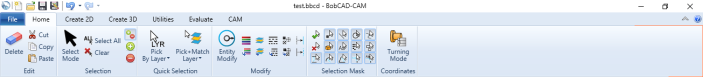
Home Ribbon
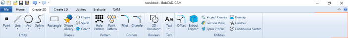
Create 2D Ribbon
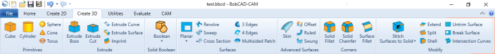
Create 3D Ribbon
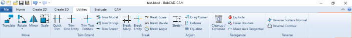
Utilities Ribbon
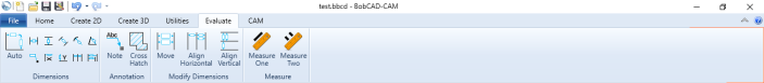
Evaluate Ribbon
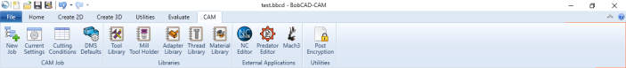
CAM Ribbon
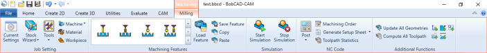
Contextual Cam Ribbon
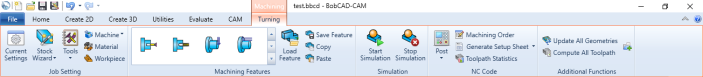
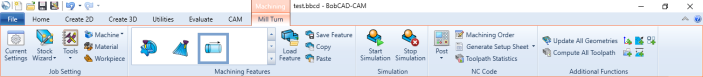
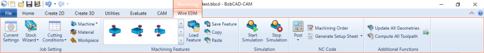
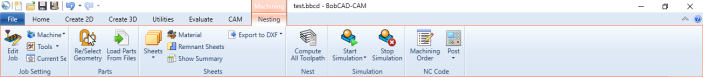
This section highlights how, now, all the functions of CAM will be available
in the ribbon bar. When a job is began, and an item in that job is given focus, the contextual CAM ribbons come into play. These allow you to access everything normally only available through a right-click in the CAM Tree. Everything needed for the job is in plain sight, right on the ribbon.
Mill Contextual Ribbon
Lathe Contextual Ribbon
Mill Turn Contextual Ribbon
Wire EDM Contextual Ribbon
Nesting Contextual Ribbon
Document Toolbar
Whether you are working with 2, or 3D, and whether it's CAD, or CAM, one thing you will always want access to, is your view options. In this version, we have added a Document Toolbar to the top of the graphics area so all your view options will be at your fingertips no matter what you're doing. This will help reduce those mouse-miles considerably!
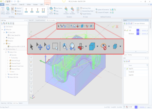
The View options the Document Toolbar provides are:
- Selection Mode
- Pan
- Rotate
- Zoom Window
- Fit All
- Zoom Previous
- All Standard and ISO Views
- Shaded, Transparent, and Wireframe
- Blank, Unblank, Hide All Images, and Hide All Embossed Model
- Ortho Projection, Antialiasing, Surface Normal, Shading Smooth, Polygon Shaded, and Polygon Lines
Backstage
In the past, File options, like Save and Merge, Preference options, like Customize, and Settings Part and Default, along with the Help options, like access to the Help system, and Licensing options, were all found in different areas of the software. This was somewhat counter-intuitive, and has been remedied in this latest version of BobCAD-CAM. All of these options can now be found in an area called the Backstage. Simply click on File, and everything that has to do with files, or the modification of the software itself can be found in one, easily manageable location. The Backstage give you access to:
- New
- Open
- Save
- Save as
- Merge
- Close
- Recent Files
- Themes
- Help
- Settings Part
- Settings Default
- User Profile
- Customize Shortcuts
- Exit
New Docking Strategies
In past versions of BobCAD-CAM, there were several managers available to you. These were the BobCAD Live Manager, the Measure Entity Manager, and the main two, which were referred to as the Layer-UCS-Post Manager, and the Data-CAM Tree Manager. The Layer-UCS-Post Manager is where you would work with Layers, User Coordinate Systems, and posted code. The Data-CAM Tree Manager is where you wold work with the Data Entry Manager, the CAD Tree, the CAM Tree, and BobART. The position of each of these managers was customizable... to a point. In the past, these managers, could either be left as floating, or be placed on the left, or right of the application. When more than one shared the same side, they could be placed either next to, or on top, of each other. Now, not only can you place these managers on the top, or bottom, of the application, but the tabs of what used to be the Layer-UCS-Post Manager, and the Data-CAM-Tree-Manager, are no longer locked in those positions. You are now able to reorganize the tabs in a shared pane, or completely pull out a tab and leave it floating, dock it by itself, or dock it as a tab in an existing pane.

User Profiles
With the nearly unlimited customizations obtainable with the various docking managers, you may find you certain arrangements works a little better for particular kinds of work. For instance, maybe when creating a CAD model, you may prefer a layout where the UCS, Layer, CAD Tree and Data Entry Managers are all open and available, but prefer the CAD Tree, and the UCS Managers to be hidden while working with the CAM side of things. Maybe you even keep things in only one arrangement, but another user also works on the station and prefers his own layout. Now, BobCAD-CAM offers the means for various layouts to be saved, and loaded again at any time! Now, every layout you may use can be saved, renamed, loaded, or deleted any time you choose.
Quick Access Toolbars in Managers
In many of the Managers, there are actions that are performed frequently. In the Layer Manager, for example, you may want to add a new layer, or delete an existing layer. In the CAD Tree Manager, you may want to edit, suppress, or rename a feature. In the past, these options were only available by right-clicking in the manager. Now, these managers give you access these common functions in a quick access toolbar at the top of each!
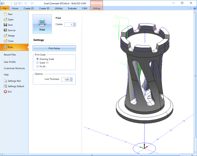
Print Dialog
In this version, even the print dialog has been improved! In previous versions, the print preview was only available by selecting it specifically. In this version, the preview is front and center as you choose your print options. Another huge improvement is the addition of the Line Thickness option. Lines, by definition, have no thickness, and over the years, printers have gotten better and better at representing this in the final product, creating printed lines that are nearly invisible to the eye. That's why, in our latest release, we've introduced the ability to set a thickness to the lines, so all of your printed lines, arcs, and splines can come out just as you want them. Lastly, and by popular demand, we have completely redone how our Print Scale options work. Your Drawing Scale will print the current view, and the amount of zoom being used currently in the graphics area. The Scale 1:1 will now print items to their actual size, and the Fit All option will squeeze the contents of the graphics area down to a zoom level that will accommodate a single sheet of paper.
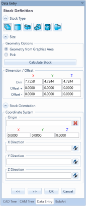
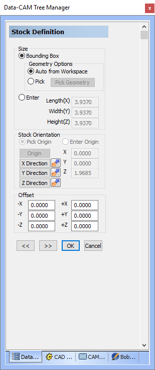
Stock Wizard
The Stock Wizard has been revisited to make stock creation as smooth an intuitive as possible. First, the Stock Type and Stock Definition pages have been combined, so that all of your stock types are available to choose from on the same page you'll define their size on. Also, all the parameters have been reorganized to group like items more logically. For instance, why set the size of the stock at the top of the stock definition page, and then add a size offset at the bottom? Both are setting the size of the stock, and now they're both in one Dimension / Offset group. Instead of jumping here and there and double checking your map, this stock wizard has an easy flow that new comers, and veterans alike will love!
| BobCAD-CAM V31 | BobCAD-CAM V30 | |
|
|
Settings Part / Default Updates
While most of the Settings Part, and the Settings Default dialogs have remained untouched, we have done a little reorganization in regards to the dimensions, and have added the additional settings now found in the updated Dimensions dialog.
- The options for the width, and length of the arrows, along with the leader extensions options for the Outside Arrow has been moved to the Arrows page.
- On the Dimension page, the Font options have been separated from the Dimension group, into its own Font group.
- The Font options have been updated to include font type as well. Choose between Windows Font and BobCAD Font types, then set the specific font to be used.
- The option Extra Zeros, which dictates whether trailing zeros are used in dimensions, has been added to the Dimension and Tolerance groups.
- The new tolerance options, Custom, None, Single, and Symmetric, have been added to the Tolerance group.
General
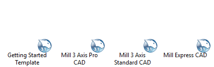
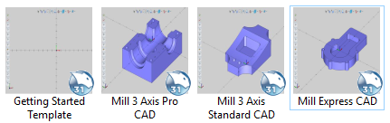
File Preview
In the past, .bbcd files would appear with nothing more than a BobCAD-CAM icon in front of the file name. For those of us that are not super organized with our files, finding the correct file in Windows Explorer could be a little frustrating. Now, BobCAD-CAM files have a preview in place of the icon that shows a screen shot of the user interface, making the search for the proper file easier than ever.
| Files without Preview | Files with Preview |
|
|
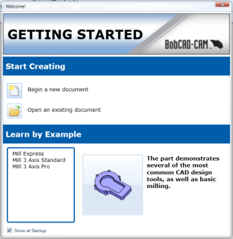
Getting Started dialog - Show at Startup
The Getting Started training is an awesome way to teach newbies the software, but after they've learned, the Getting Started dialog itself simply becomes a startup annoyance. In this version of BobCAD-CAM, we've done you the courtesy of giving you a way to say goodbye to that dialog. When you start up BobCAD, and the Getting Started dialog appears, simply click the Show at Startup option at the bottom left of the dialog, to keep it from launching when you open the software.
CAD Enhancements
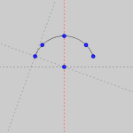
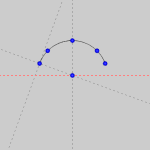
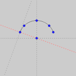
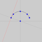
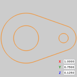
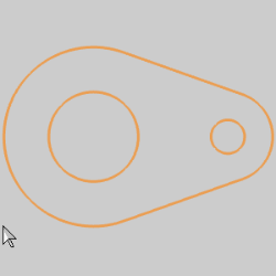
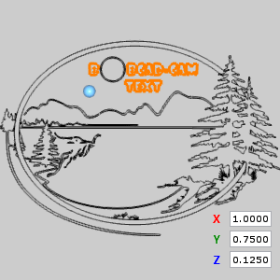
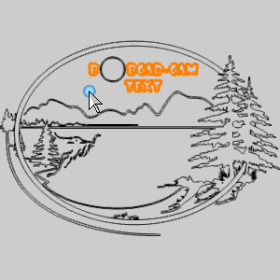
Construction Geometry
Construction Geometry has been added to the version V31 release to make the creation of CAD geometry easier than ever before. Just like the Snap Increment function, construction geometry can be turned on and off easily by clicking the ![]() icon at the bottom of the user interface. While it's on, construction geometry can assist you with many things:
icon at the bottom of the user interface. While it's on, construction geometry can assist you with many things:
- In the past, creating straight lines while sketching required you to select the "Horizontal / Vertical" option in the dialog. Construction geometry points these locations out for you automatically.
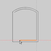
- In the past, it was impossible to tell where the tangent point on an arc was while sketching a line. Construction geometry shows you exactly where the tangency is.
- In the past, finding a point of intersection required an entirely different function. Construction geometry will show you when you're lined up with each!
| Nothing in Line | Horizontal Arc Center | Horizontal Line End | Intersection |
|
|
|
|
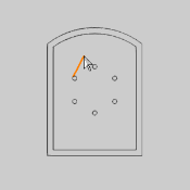
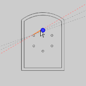
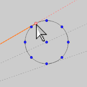
- Hovering over an arc can provide a great deal of data.
| Vertical Arc Center | Horizontal Arc Center | Perpendicular to End | Tangent to End |
|
|
|
|
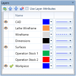
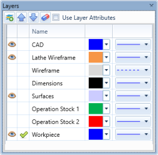
New Layer Manager
In the past, the Layer Manager was very rigid. There was no changing the order of the layers. There was certainly no changing the order of the columns. And, if like many users, you organized your layers by color and line style, then it was up to you to change the active color and line style each time you switched to that layer, and then again when you switched from that layer. The new Layer Manager does more than just provide an improved look to the interface, it changes everything! This new interface allows you to adjust the order of the layers in the list and even the order of the columns themselves! In this version of BobCAD-CAM, you also have the option to have each layer utilize its own assigned color and line style! When each layer is created, it is automatically assigned whatever color and line style is currently in use. You can, at any point, easily choose a different color and/or line style to associate with a particular layer, and even when the active color or line style is changed, each layer will maintain its current assignment. These colors, and line styles, are then only utilized when the Use Layer Attributes option is enabled. At that point, any time you make a layer active, its color and line style will be used as the active color and line style.
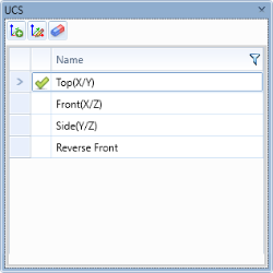
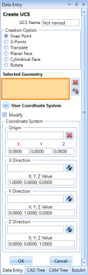
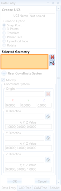
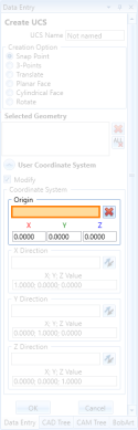
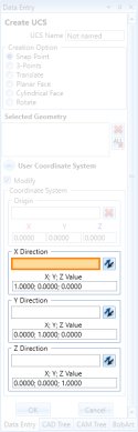
New UCS Manager
The UCS Manager has been updated to include quick access buttons to allow you to get to frequently used commands even easier.

The options for UCS creation, available in the Data Entry manager, have also been expanded to give users the same functionality which has worked so well for setting the position, and orientation of the Machine Setup. As you can see in the images below, we have added the Selected Geometry list, and allowed for both, geometry selection, and data entry, for both, the origin, and the axial directions.
Wireframe Geometry Creation
Just about every one of our wireframe geometry creation tools have been enhanced using
the functionality we introduced in our last version. In V30 we introduced picking boxes to our 3D creation tools, and it was a huge hit! Finally, if you picked the wrong entity for the function, or picked them in the wrong order, you didn't need to cancel the function and reopen it to start from scratch; you simply update the items in the picking boxes and continue on. In our latest release, we've added that same ease of use to our 2D creation methods. Not only that, but the functions that used to allow you to choose whether you were picking a location in the graphics area, or entering a location with data entry, now allow you to do a combination of both without even having to click a Pick/Enter button; simply pick a point in the graphics area, and update the data entry values as needed, or vice versa!
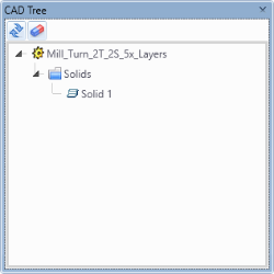
What's more is; we have used many of the customer requests from the past to revisit how your basic entity types, like
points, lines, arcs, splines, and more are created within the BobCAD software. Usually, when creating a particular entity type, you're creating more than one. And when you're creating more than one, you usually end up needing different creation methods. In the past, using a different creation method meant finding another icon in the toolbar, then launching it to access its dialog in the Data Entry Manager. In BobCAD-CAM V31, each entity type shows all possible Creation Options directly in the Data Entry Manager! We also went a step further to make creation much easier:
- In some cases, we have combined the functionality of several entity creation functions into a single creation option. For instance:
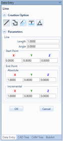
The new Line Creation Option does the work of the old Line Sketch, Line Coordinates, and Line Join functions! - In some cases, we have even created brand new methods of creation that have never been possible in BobCAD. For instance:
Whereas in the past we have only had one way to create a rectangle, there are now five creation options to give you access to the perfect tool for any situation you may encounter.
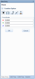
Points
The point functions have been condensed so that much the power, and functionality of several functions is now available in a single function! Below is a map showing which functions have been boiled down to a single function.
![]()
Lines
The line functions have also been condensed, and, just like the points, the functionality of several of the line functions are now available in a single function! See the map below to see which functions have had their functionality funneled into a single function.
![]()
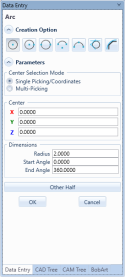
Arcs
While the arcs have had three of their functions combined into a single function, we have also created two brand new creation types! The 3 Points Center/Endpoints, and the 3 Points Endpoints/Radius creation options are brand new ways to create arcs in BobCAD-CAM. We also solved one of the little annoyances that comes with making partial arcs. In the past, you could enter a start and end angle to create partial arcs, but occasionally those values would be typed in the wrong order, giving you the exact opposite of what you were hoping for. In these cases, you would just need to swap the values and retype them in the correct fields. Now, we offer a simple "Other Half" button to do this for you automatically!
- 3 Points Center/Endpoints - allows you to set the center of the arc with one click, the radius and the start angle with the next click, and the end angle with the last click.
- 3 Points Endpoints/Radius - allows you to set the set the start and the end of the arc with the first two clicks, and then drag the radius out and set it with the last click.
![]()
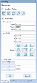
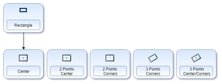
Rectangles
While the standard rectangle creation method has been kept, four brand new creation options have been made to give you access to the perfect creation methods for any situation!
- 2 Points Center - allows you to click once to set the center of the rectangle, and click a second time to set the length and width simultaneously.
- 2 Points Corners - allows you to click once to set one corner, and click a second time to set the opposite corner.
- 3 Points Corners - allows you to click once to set one corner, click a second time to set the perpendicular corner, and click a third time to set the next perpendicular corner. This creation options also allows you to set the angle of the rectangle during creation.
- 3 Points Center/Corners - allows you to click once to set the center, click a second time to set the length of the rectangle, and click a third time to set the width of the rectangle. This creation options also allows you to set the angle of the rectangle during creation.
Splines
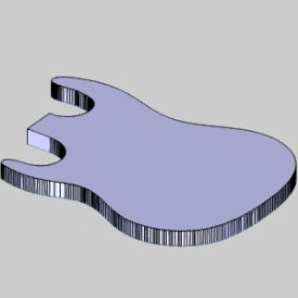
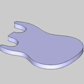
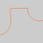
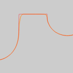
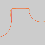
In BobCAD-CAM version V31, splines have been upgraded to give you an enormous amount of control! One of the most frequent uses of splines are to cleanup geometry that could otherwise cause some issues. Perhaps when working with a custom file you notice, when extruding a closed chain, that the chain is actually made up of tiny line segments creating a jagged surface. Splines are a perfect fix for this!
|
Extrusion with Line Segments |
Extrusion with Spline |
|
|
|
In previous versions, you could select the geometry to be made into
a spline and select either, the Approximated, Interpolated, or Fit spline
function, and a spline would be generated automatically based on the selected
geometry. The only issue was, if you didn't like it, you would need to
delete the result, and then test the next result until you found the one
that worked the best. Now, not only can you see a preview before you finalize
your spline, but we have combined all spline functions into one dialog
so you can simply click each option to see how the preview is affected,
and now you can even utilize the Blended spline method when applying a
spline to existing geometry.
|
Approximated Test |
Interpolated Test |
Fit Test |
Blended Test |
|
|
|
|
|

The splines now give you the control to Use End Point or Use Middle point when using the Multi-Picking method. This allows you to further hone the result of your spline, by forcing the splines to use, either, the end points of the selected entities, or the middle of the selected entities. In the image below, you can see our desired result is achieved when we utilize the new Middle Point option with our spline.
|
Blended w/ End Point |
Blended w/ Middle Point |
|
|
|


On top of all this control, we also give you the option to choose between Sketch/Single Picking, or Multi-Picking. In the examples above, we used Multi-Picking to quickly select all geometry at the same time. You can also select Sketch/Single Picking to select individual snap points or free sketch your own points. Whichever method you choose, all points and entities are now added to a Point List to allow you to highlight a point in the list, and delete it, or even move it up and down in the list to change the spline preview. Plus, when you use the Sketch/Single Picking method, we display a Coordinate group to allow you to adjust the location of individual points in the list manually. Just select a point in the list, adjust the X, Y, and Z coordinates and have the preview update in real time to see exactly how the spline will be affected.
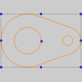
Shape Library
While the Shape Library has retained its existing selection of shapes,
we have added some extremely helpful options for the placement of the
shapes. In the past, there was only one option when it came to defining
the origin of the shape: Data Entry. Each shape had its origin, which
always referenced the bottom left of the shape's bounding area, defined
by entering values manually for its X, and Y location. Now, not only can
you also define the Z location of the origin, and, not only can you set
where that origin is referenced around the shapes bounding area, but you
can even use the sketch method to freely sketch the origin of the shape
with your mouse in the graphics area, by clicking empty space, or an existing
snap point! Once the shape is placed, you can also refine its location
further using the data entry method.
|
Origin Options |
|
|
Bottom Left Bottom Center Bottom Right Right Center Top Right Top Center Top Left Left Center Center |
|
Placement Options |
|
|
Data Entry |
Sketch |
|
|
Text Enhancements
The Text function has now been given the same ability which has proved to be so helpful in our other CAD functions. The origin of the text can be set with the existing sketch-style drag and drop method, or now, even data entry. In the past, you would type the desired text, then click okay, and then move your mouse into the graphics area to place the text. This method had a couple drawbacks. You couldn't see the text until you clicked OK, and you could only place the text with your mouse at the bottom center of the preview. Now, the preview updates in real time as you type, and update settings, and the text does not move until you click on it. That means you can move your text with a high level of precision without needing to enter another function. Once your text is placed, if it needs to be adjusted, simply alter the values of the origin with data entry!
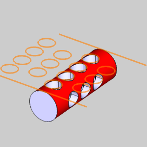
Unwrap
The Unwrap function was a huge help to people creating wrapping groups for 4 Axis jobs. Creating flat geometry representing an unrolled solid was nearly impossible without it. The only issue was it usually required some cleanup afterwards. In the images below, notice the unwrapped geometry on the left has one of its rows of holes split down the center. This is because of how the unwrap is working to unroll the geometry from a seam. Correcting this required translating geometry to move the broken pieces back together again manually. Now, with the Chain Selected Geometry option, selecting a simple checkbox will help ensure this never happens in the first place!
 Chaining Selected Geometry
|
|
|

|
Solid and Surface Creation
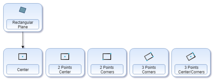
Rectangular Plane
While the standard rectangular plane creation method has been kept, four brand new creation options have been made to give you access to the perfect creation methods for any situation!
- 2 Points Center - allows you to click once to set the center of the rectangular plane, and click a second time to set the length and width simultaneously.
- 2 Points Corners - allows you to click once to set one corner, and click a second time to set the opposite corner.
- 3 Points Corners - allows you to click once to set one corner, click a second time to set the perpendicular corner, and click a third time to set the next perpendicular corner. This creation options also allows you to set the angle of the rectangular plane during creation.
- 3 Points Center/Corners - allows you to click once to set the center, click a second time to set the length of the rectangular plane, and click a third time to set the width of the rectangle. This creation options also allows you to set the angle of the rectangular plane during creation.
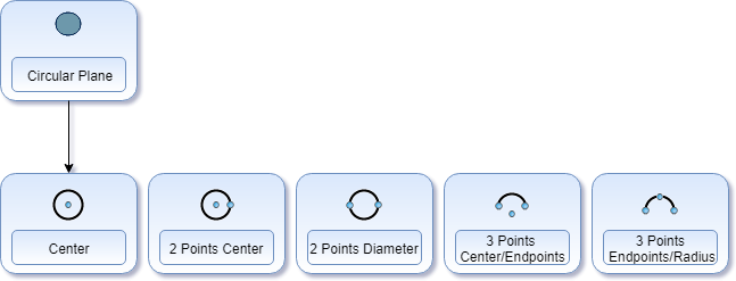
Circular Plane
While the standard circular plane creation method has been kept, four brand new creation options have been made to give you access to the perfect creation methods for any situation!
- 2 Points Center - allows you to select the center of the circular plane with one click, and the radius with the next.
- 2 Points Diameter - allows you to select two points to define the full diameter of the circular plane.
- 3 Points Center/Endpoints - allows you to set the center of the circular plane with one click, the radius and the start angle with the next click, and the end angle with the last click.
- 3 Points Endpoints/Radius - allows you to set the set the start and the end of the circular plane with the first two clicks, and then drag the radius out and set it with the last click.
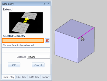
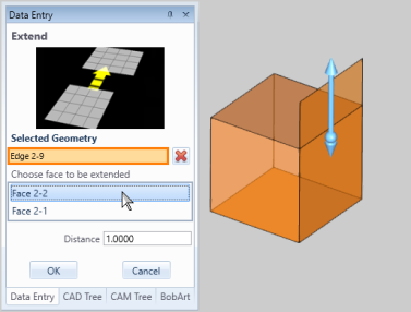
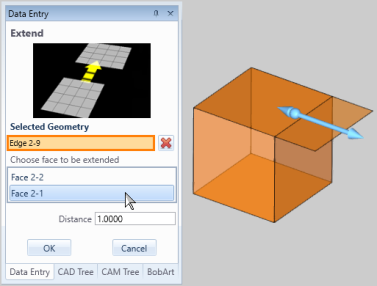
Extend
The surface edge extension function Extend, now employs the pick box section method. The function also now offers users the option to choose which surfaces face to extend when an edge is selected that is shared between two stitched surfaces.
Dimensioning
Auto Dimension
In order to dimension a print in the past, you always had to jump back and forth between multiple dimension functions to create the various dimension types needed for the print. Now, we have combined all of the main dimension functions into one incredibly powerful function which actually utilizes the selected entity types to allow you to naturally create the dimensions you want based on what you are selecting. No longer will the software just utilize snap points on entities. With the new intelligent dimension function, the actual entity information is utilized and the relationships between the selected entities produce the dimension you are looking for! And that's not all! When selecting two points, or a line that isn't perfectly vertical , or horizontal, simply altering the position of the mouse when dragging the dimension into place will determine whether that dimension is vertical, horizontal, or an Other distance, as seen in the images below.
Note
In the past, notes could be added to drawings, but they had to be created manually. This would require creating and placing text, then creating lines for the leaders, for the arrows, and then placing those lines as necessary. Now, all of this can be done simply and automatically. Enter the text, choose the leaders termination positions, and then drag the leader and text into position.
Mirror About Planar Face
In the past, the Mirror function allowed you to select a Plane, or a selected line, to use as a mirror. This meant that your options were fairly limited, unless you wanted to create a brand new UCS to force the results you were looking for. Now, in BobCAD-CAM V31, the Mirror option has a Planar Face selection option to allow you to use any surface in the graphics area as a mirror!
New G-Code Editor
The NcEditor is a brand new addition to the ModuleWorks, and BobCAD-CAM family. We have been working hand and hand with ModuleWorks to plan, develop, and test this new editor, and it's finally ready for the public. Much like the Predator Editor we included in the installation, the NcEditor comes standard, but is available to upgrade. As you might expect though, some serious improvements have been made.
Standard NcEditor
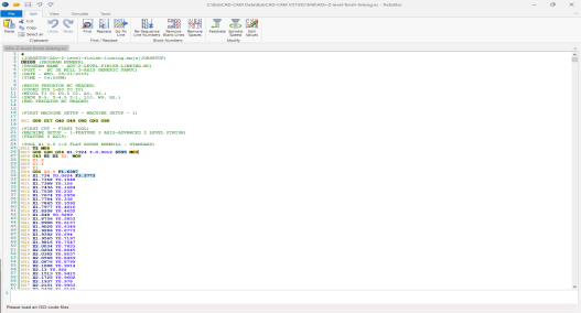
Although the Predator Editor came standard with BobCAD-CAM, it was basically just Notepad with DNC capabilities. If you wanted to use syntax highlighting, you needed the Pro Editor. If you wanted to remove sequence number, or resequence the code, you needed the Pro Editor. If you wanted to adjust feedrates, and spindle speeds without having to search through the code, you needed the Pro Editor. Now, in the NcEditor, all of this and more is available in the Standard version!
Pro NcEditor
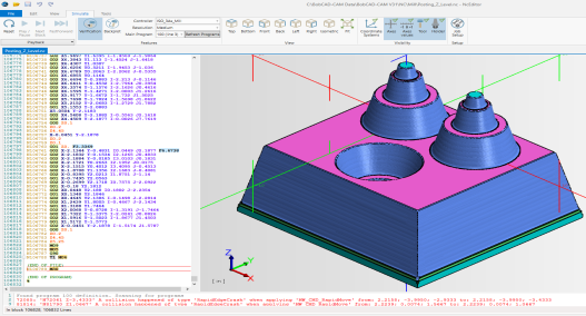
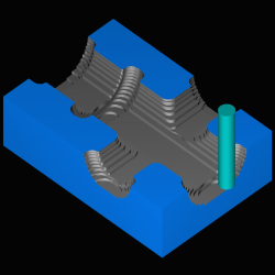
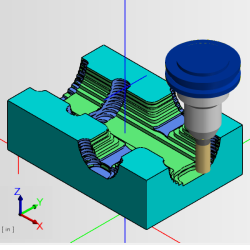
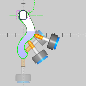
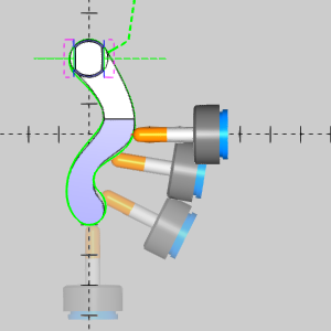
Of course, the main reason you want to upgrade to the Pro version of an editor is to be able to backplot the code, and verify it to see the effect of the actual code on the stock. And of course you can do this in the new Pro NcEditor, but the difference between verifying in Predator Editor and the New NcEditor is night and day. Just take a look at what you see in the graphics area:
| Predator Editor | The new NcEditor |
|
|
From the simple things, like being able to see a gnomon with a unit indicator, being able to toggle the visibility of the axes, axes values, and the tool itself, to the big things, like being able to actually see the tool holder and arbor, being able to see your assigned coordinate systems, and having each operation leave a distinct color in the stock. These are things that our Predator Editor simply could not do.
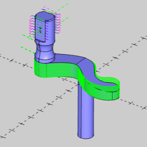
The NcEditor Job Setup
The old editor had several drawbacks. One of the issues was that you could not see the tool holders, and arbors, or their effect on the stock. Another issue was with trying to view g-code programs that weren't posted from BobCAD-CAM: If you had an old job you wanted to view, you essentially had write a bit of code to paste into your g-code so Predator could show you the effect of the tool. This wasn't ideal, since you had to be familiar with the exact format to use when coding, there was no way to support viewing the holder and arbor, and the simulation treated the tool flutes and shaft as a single item. In the new NcEditor, this is all handled with an intuitive user interface called the Job Setup. The job setup, which is set automatically when launched from BobCAD-CAM allows you to also easily set up older programs by allowing you to:
- Create a new job setups to use.
- Save job setups to use later.
- Select a Machine.
- Assign a target part, and set its color.
- Assign stock geometry, and set it's color.
- Use the Tool Manager section to:
- Create 12 different tool styles.
- Create Arbors.
- Create Holders.
- Create Tool Assemblies.
- Create Adapters.
- Use the Setup section to:
- Create Stock.
- Create Tool Assignments.
- Create Work, and Tool Offsets.
With all of this power, the new NcEditor will make verifying, and backplotting g-code easier than ever!
CAM Enhancements
General CAM
Advanced Feedrates
Now, in BobCAD-CAM V31 we are offering a huge amount of control over your feedrates by introducing the Advanced Feedrates page to many of the Mill and Lathe operations.
Lead-in and Lead-out Feed Control
One of the most important cuts in an operation, is the initial Lead-in. The feedrate used for this cut is also very important, and can sometimes differ quite a bit from the rest of the operation. In the past, there was no way to control these moves individually. You could always set plunge feedrates, and the overall feedrates, but leads would always simply inherit the overall feedrate. Finally, BobCAD-CAM offers the ability to control the feedrates for lead-ins, and the lead-outs specifically. This will be big help for jobs run on Lathes, Mills, Lasers, Plasmas, and Waterjet machines.
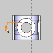
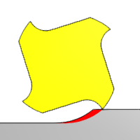
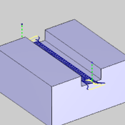
Link Feedrate Control
In toolpath, links occur everywhere one cut needs to connect to the next in the same region. In the image below, you can see an Advanced Z Level Finish operation, with its linking moves in yellow: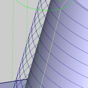
In the past, these moves have always been assigned the same speed as the overall feedrate of the operation. Now, BobCAD-CAM allows you to have control over the feedrate of these linking moves. The following operations will allow control over the link moves when the particular pattern is selected.
| Feature | Pattern |
|---|---|
|
Advanced - Parallel Advanced - Offset In/Out Advanced - Morph Advanced - Adaptive Roughing |
|
| Facing | Adaptive |
| Advanced Rough |
Parallel Offset In/Out Morph Adaptive |
| Advanced Z Level Finish |
Rapid Feedrate Control
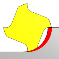
Now you can gain control over the speed at which rapids run on your machine! This can help enormously when fast moving rapids cause elbows in the rapid moves from one area to another. This is sometimes referred to as "Dog Leg Rapids", and occurs when one axis reaches its coordinate value before the other. When this occurs, what appears to be a straight rapid move in the graphics area, can have an angle to it. This isn't a big deal, until your moving close to fixture clamps as seen in the images below:
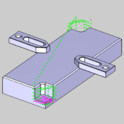
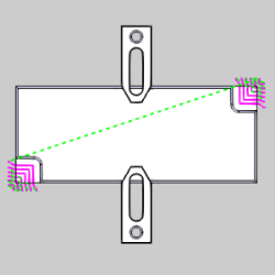
In cases like these, unexpected dog legs can cause a big problem, and will not be seen in the toolpath! The image below has been altered to show what could happen on the machine.
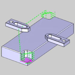
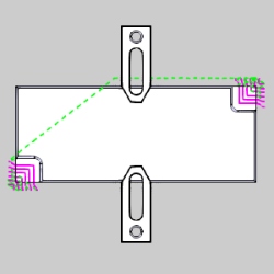
When this occurs, in both Mill, and Lathe jobs, being able to set a feed value to the rapids can completely correct these issues!
Adaptive Feedrate Control (Volume Based)
Another benefit of the Advanced Feedrate Control options is the Adaptive, or Volume Based, feed control. With the Adaptive feedrate control, you can set a Min, or even a Min and Max Feedrate %, so the feedrate will automatically adjust based on the volume of material the cutter is engaging!
| Feature | Pattern | Type |
|---|---|---|
|
Advanced - Parallel Advanced - Offset In/Out Advanced - Morph |
Min Feedrate % | |
|
Advanced - Adaptive Roughing |
Min & Max Feedrate % | |
| Facing | Adaptive | Min & Max Feedrate % |
| Advanced Rough |
Parallel Offset In/Out Morph |
Min Feedrate % |
| Advanced Rough |
Adaptive |
Min & Max Feedrate % |
Radial Chip Thinning
Radial Chip Thinning is something many machinists are familiar with. Since most of the heat from machining is actually removed with the chips, keeping the chips at their largest possible size can be a huge help in saving tool life. In essence, the smaller your stepover, the faster your feedrate should go.
| 12% Stepover | 50% Stepover |
|
|
That's an easy thing to program when you're working with straight toolpath, but what about when working with curving toolpath? Well things can get tricky there. When using the Adaptive Roughing Pattern for Pockets, or the Advanced Rough operation, you are now able to set a minimum and maximum feedrate percentage for Radial Chip Thinning.

| Feature | Pattern | Type |
|---|---|---|
|
Advanced - Adaptive Roughing |
Min & Max Feedrate % | |
| Advanced Rough |
Adaptive |
Min & Max Feedrate % |
Conventional Feed Control
In the past, when using the Zig Zag method method for the Adaptive Pattern on the Advanced Pocket, and the Advanced Rough operations, we would utilize the overall feedrate for both, climb, and conventional cuts. Now, users are provided with the ability to set a separate Conventional Milling Feedrate.
Edit Operations from the CAM Tree
In the past, when a feature contained multiple operations, the only way to edit the individual operation was to right-click on the main feature, and then navigate through the wizard to get to the pages for that individual operation. In this release, we've provided a means to jump directly to an individual operation of the wizard! In the CAM Tree, right click on a particular operation and click Edit. Now, when the wizard launches, it will open on the tool page for that exact operation.
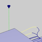
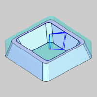
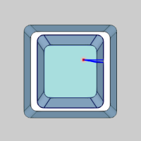
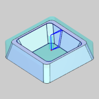
Start and End Indicators
In many cases, once toolpath has been created, the users first concern is where the operation is starting and ending. Having to wait for the simulation to launch just to verify that was never fun, and when we created the Backplot options to view tool movement directly in the graphics area, it was a huge help with this. In this version however, we've gone a step further and created the Start and End Indicators. Just click on an operation, and along with the toolpath highlighting in the graphics area, the Start and End Indicators will now show where the toolpath starts and ends.
Mill
Mill Express
Drag Knife
A brand new type of feature is now available in the BobCAD-CAM V31 release: The Drag Knife feature! Drag Knives are used in the inlaid veneer industry, the artwork industry, and by everyday hobbyists to cut things like snowboard and ski base materials, wood veneer for inlay/marquetry artwork, leather, carbon fiber pre-preg laminates for aerospace, military, and automotive components, cardboard for custom packaging, and much more. Whether you want to perform delicate veneer inlay work or cut out cardboard boxes with your CNC router, the Drag Knife feature is the right feature for the job.
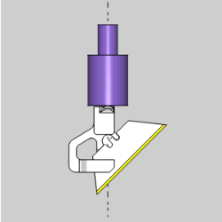
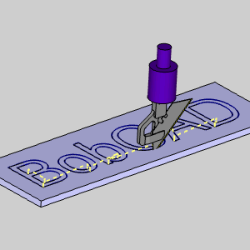
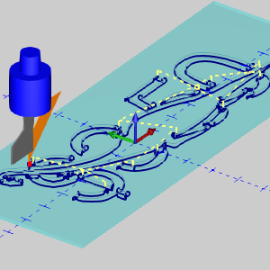
The Drag Knife also supports the Backplot function, which allows you to view the tool motion directly in the graphics area!
Mill 3 Axis Standard
New Pocketing Patterns
In the New BobCAD-CAM V31, we offer two main pocketing pattern types; Standard Pocket & Advanced Pocket.
 Standard Pocket
|
|
|
While the Standard Pocket type still uses the same basic patterns, the Zig Zag pattern, is now called Parallel. In the Advanced Pocket, we offer two brand new patterns: Offset Pocket In, and Morph Spiral.
Advanced Offset Pocket In
In order to put another tool in your toolpath arsenal, we are providing you with, yet another method of cutting a pocket. When using the Advanced Pocket with a Offset Pocket In, rather than the standard method of starting from the outside, and working your way in, this toolpath starts on the second row, so when the tool is cutting in full engagement it stays well away from the finished wall. The toolpath then works its way in, and finally comes back to tackle the first row, leaving much cleaner material behind.
Morph Spiral cutting for Pocket
A new pattern option has been created for the 2 Axis Advanced Pocket. By popular demand, the Morph spiral has been created to maximize the efficiency of the offset pocket. By morphing the offset shape into a spiral we help eliminate the slowdowns of those pesky linking motions.

Smooth Connections for Parallel roughing
When cutting 2 axis pockets with the Zig Zag pattern, the only option to link passes has been a direct route. This is not always ideal, since hard angle changes always cause a lot of slowdown. To stop moving in one direction, you need to slow down, to begin moving in another direction, you have to start from a stop. In BobCAD-CAM V31, the Zig Zag pattern, which is now called Parallel, offers a new parameter, called Smooth Connections. Smooth Connections allows you to eliminate the hard angles between passes, and replace them with a radius value to keep the tool moving and avoid the slowdown of those hard angle changes.
Breakthrough overlap for Adaptive Roughing
When creating an open pocket using the adaptive roughing method, we would sometimes find ourselves in situations where the toolpath didn't quite remove enough material from the opening before coming back with cleanup passes to remove the left over amount. This was easy enough to correct, but it did require the creation of new geometry to select for the feature so you could force it into doing what you wanted. An easy fix, but not easy enough. Now, we've added a simple slider control in the Parameters page called Break through amount. This allows you to set the slider to either Less, or More, which will set how much material will be left for the cleanup passes to handle.
Mill 3 Axis Pro
Advanced Rough
In the past, only three cut patterns were available when using the Advanced Rough. Now, in BobCAD-CAM V31, we offer a total of 5 cut patterns to give you the tools to get the job done the way you want.
- Offset Out
- Offset In
- Morph Spiral
- Parallel
- Adaptive Roughing
Advanced Rough Offset In Cut Pattern
In order to put another tool in your toolpath arsenal, we are providing you with, yet another method of clearing an area. When using the 3 axis Advanced Rough with a Offset Pocket In, rather than the standard method of starting from the outside, and working your way in, this toolpath starts on the second row, so when the tool is cutting in full engagement it stays well away from the finished wall. The toolpath then works its way in, and then comes back to tackle the first row, leaving much cleaner material behind.
Morph Spiral Cutting Pattern
A new pattern option has been created for the 3 axis Advanced Rough. By popular demand, the Morph spiral has been created to maximize the efficiency of the cuts. By morphing the offset shape into a spiral we help eliminate the slowdowns of those pesky linking motions.
Smooth Connections for Parallel Cut Pattern
When cutting with the Parallel pattern, the only option to link passes has been a direct route. This is not always ideal, since hard angle changes always cause a lot of slowdown. To stop moving in one direction, you need to slow down, to begin moving in another direction, you have to start from a stop. In BobCAD-CAM V31, the Parallel pattern offers a new parameter, called Smooth Connections. Smooth Connections allows you to eliminate the hard angles between passes, and replace them with a radius value to keep the tool moving and avoid the slowdown of those hard angle changes.
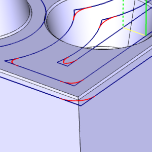
Advanced Z Level Finish
Start Point Control
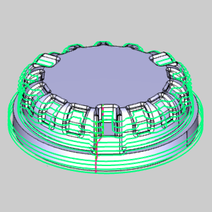
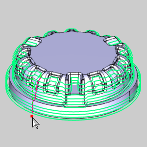
With all the power available in the Advanced Z Level Finish, there was one area it was lacking; the toolpath calculation determined the start point. When programming a part, the more control you have, the better. That's why with our version V31, we now offer control over exactly where your Advanced Z Level starts! The Start point can be selected from the graphics area, or it can even be entered manually.
| Undesirable Start Location | Adjusted Start Location |
|
|
This works for the regions as well! Whereas the above example has only one start point, operations with multiple regions have multiple start points as in the examples below. Notice the original part with toolpath, and notice the start points being affected with the selected start points. 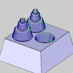
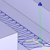
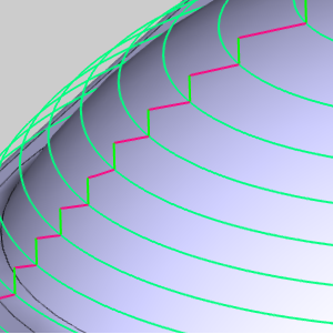
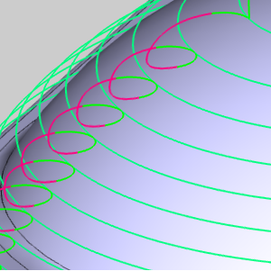
New Linking Options
Along with the control to set the start point of the Advanced Z Level Finish, we are also providing brand new methods of linking one pass to subsequent passes. Along with the links that have been available for the Advanced Z Level Finish, you can now also use Horizontal/Vertical, and Spiral.
| Horizontal / Vertical | Spiral |
|
|
Shift Subsequent Passes
Normally, no matter which linking option is selected for the Advanced Z Level Finish, the start of the next pass is basically straight down from the end of the previous pass. This isn't always an issue for most, but in some cases, the best practice is to move the start point of the next pass, so an obvious line isn't visible in the final product. In our latest release, you can do just that. By selecting the Linking Position option, you can enter a value, and the start of the next pass will be offset by that amount. This is a great way to "blur the edges", and get the best finish possible.
| Default | Shift subsequent passes by: |
|
|
Improved Round Corners / Smooth Corners Calculation
Not only do we create brand new tools and features for our releases, but we are also constantly working to make what we have better, for us, and our customers. In this version, one of those improvements is to the calculation of our Round Corners option found in the Advanced Z Level Finish, along with the Advanced Planar, and the Smooth Corners option found in the Advanced Rough.
Expand the Rest machining area
Since the introduction of Rest Machining in BobCAD-CAM, users have been making the most of it. Being able to create an operation which only focuses on the areas left by a larger tool on a previous operation has certainly proven invaluable! The only thing we noticed along the way, however, is it can be a little too exact. In machining, having a little overlap is usually the way to go, in order to keep things as clean as possible. That's why, in BobCAD-CAM V31, we are introducing the Expand Rest Area option. This provides the ability to extend the area that will be rest machined in order to provide enough overlap to have it machined well.
The Expand Rest Area options is now available in the following operations:
- Advanced Planar
- Advanced Z Level Finish
- Project Curves
- Equidistant
Mill 3 Axis Premium
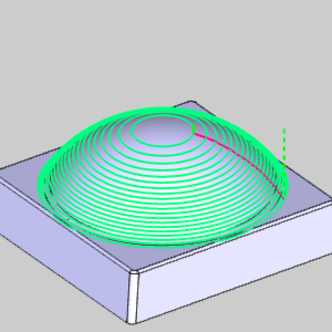
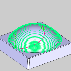
Multiple Surfaces for Flowline
When we introduced the Flowline toolpaths, it changed the way the toolpaths we calculated, clicking one surface and having the software do the work was a lot easier than selecting several different pieces of geometry to help define the toolpath. However, the only problem with the flowline toolpath was that it only worked for one surface at a time. Needing one single surfaced toolpath is definitely the exception and not the rule. Normally toolpath needs to cover several different surfaces. With the new flowline options, you can select multiple surfaces at once. Although the surfaces are technically still calculated individually, the toolpaths are then linked together to create one continuous operation.
Lead In – Reverse orthogonal line
The Reverse Orthogonal Line has now been introduced to offer the ability to change the direction of the orthogonal line lead when needed.
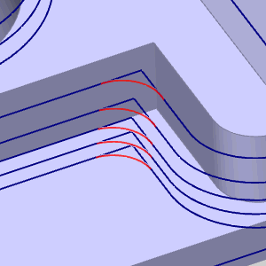
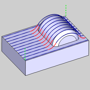
Automatic Arc lead
Toolpath cutting moves, and retract moves can sometimes feel at odds with each other. In an effort to create smoother overall toolpath, the Automatic Arc Lead offers a way to blend out of the cut move, and into the linking move with a tangential arc. The Automatic Arc consists of two splines. The first spline leaves the surface tangentially in the surface normal direction of the relinking. The second spline connects tangentially into the plunge or retract motion using the tool axis tilting orientation.
Mill 4 Axis Pro
Tool Axis Smoothing
When tools move through a valley of surfaces, the valley can cause to tool to make wide changes in angle when attempting to cut normal to the surfaces. In order to allow a smoother transition between these areas, the Smoothing options have been added to the Tool axis control page.
| Isometric View of the part | |
|
|
| Top View Smoothing Off | Top View Smoothing On |
|
|
Mill 5 Axis Pro
Multiaxis Roughing
Dynamic Holder Collision checking against stock
This is a new option in the Gouge Check page of the Multiaxis Rough operation. In our version 30 release, we presented this option for our 3 Axis Pro module. Now, in BobCAD-CAM V31 it is available for the Multiaxis Roughing toolpath. Unlike other gouge checking options which check for gouges once the toolpath has been calculated, and then trim and relink, this option checks for gouges during the toolpath calculation. You can now check holder with: In Process Stock, or Machining Surface. In Process Stock constantly updates what stock would be remaining as it is removed by the tool. This is extremely helpful, since, as the stock is removed, it is no longer a concern for collision. The Machining Surface option is most helpful when the model extends beyond the stock.
Extend cuts for stock
When using the Morph between ceiling and floor strategy of the Multiaxis Roughing, you can now choose to extend the toolpath beyond the selected ceiling surface with the Extend cuts for stock option. This can be found in the Advanced section of the Roughing page. This option can be used to extend the morph toolpath to the top of the stock material when it is located above the ceiling surfaces.
Swarf
Normal to Guide Curve
The tool axis is oriented normal to the guide curve.
Wire Enhancements
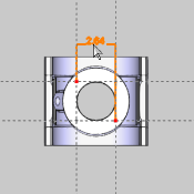
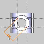
Perpendicular to Closest
Normally when people are cutting with a wire EDM machine, the start point is known, and the user wants to go straight (perpendicular) from the start point, to the closest entity. And, for some time now, BobCAD-CAM has offered wire users the ability to select a particular point to start from. The only drawback has been that the next location to move to was always the start of the selected chain, which might not lead to a perpendicular cut from the start point. That meant, a little CAD work might go into getting the desired results. In this version of BobCAD-CAM, we offer a Perpendicular to Closest option when using the Select Point lead option. Now, regardless of the geometry's start point, the user can choose an option to get the fastest path to cutting the geometry.
| Top View | ISO 7 View | |
|
|
|
|
|
Perpendicular to Closest |
|
|
Posting Enhancements
A large amount of attention was put on the milling posting engine in order to optimize the code output for 4 and 5 Axis posting. We now also provide the ability to control your coordinate output modes depending on whether you are using standard machining, indexing/positioning, or simultaneous machining. Other major enhancements include:
Transform Plane Output - Fanuc G68.2 or Equivalent
Each controller may use a different name for it, but whether your controller refers to it as Tilted Work Planes, Transform Planes, Slope Machining, or anything else, what it actually does is shift the work coordinate system to make things possible which, otherwise, would not be. For instance, drilling canned cycles cannot be output if the tool is not aligned with the Z axis of the coordinate system. By using a Transform Plane, we can shift the coordinate system to make this possible. When an operation is being done on an indexing system, most controllers aren't able to use machine compensation. By tilting the coordinate system, the controller is able to tell exactly where to put the tool to compensate properly. In many cases, machinists need to make adjustments to jobs on the fly, but on each and every job, it is always good to be able to look at the code and know exactly what to expect. This can get pretty tricky when working with jobs that aren't completely flat though. Simple coordinates can get pretty tricky! Look at the part below; a simple profile, when done on an index system can have pretty confusing X, Y, and Z coordinates called:
| Simple Profile | Coordinate System |
|
|
|
| Output without Transform Plane | |
|
N13 G01 G93 Y-0.4697 Z-0.3536 F3.3369 N14 Y-0.6464 Z-0.5303 F6.6738 N15 X0.125 N16 Y-0.4697 Z-0.3536 N17 X-0.125 N18 G00 Y-0.7879 Z-0.0354 N19 Y-1.1187 Z0.2955 |
|
Now, let's take a look at how easily that code can be read, and even updated, if we use a transform plane.
| Simple Profile | Coordinate System |
|
|
|
| Output using the Transform Plane | |
|
N13 G68.2X0.000 Y-0.7.48 Z-0.2652 I00. J45. K00. N14 G53.1 N15 Y-0.125 N16 Z0.200 N17 Z0.100 N18 G93G01Z-0.250 F3.3369 N19 Y-0.125 F6.6738 N20 X0.125 N21 Y0.125 N22 X-0.125 N23 G00 Z0.2 |
|
Origin Tracking
The Move List Writer, of the Multiaxis Posting page, has had its Move List Coordinates group upgraded. The Move List Coordinates now offer the ability to have different settings for Standard, Indexing / Positioning, and Multiaxis Simultaneous Motion outputs. Along with the available settings, in BobCAD-CAM V31, we now offer Origin Tracking!
| G43 | TCP | Origin Tracking (DWO) |
|
|
|
Simulation Enhancements
Split Simulation into multiple views
Usually, when simulating, users have a couple of different areas of the part they would like to focus on during the simulation. Whether it's to check the tool angle against the material, or to make sure tool movements between cuts are as close as possible, while still being safe, the result is the same; watching the simulation over and over, from different angles, to make sure everything is the way you want it. This can be a little frustrating when you finally rotate the view into the perfect angle, then need to check another view, only to have to try to get back to that same view again later. Now, this can be done with ease! In the View ribbon, click the down arrow under Viewports and choose between  4 views,
  3 views,
  2 rows, or
  2 columns. Now several views can be covered at once, and those difficult to get to views, can be left alone while other views are adjusted.
Double Click Toolpath
When simulating your part, trying to find information on a certain area of toolpath can be frustrating. It usually requires adjust the speed bar, pressing play, trying to stop soon enough, and then slowly stepping through the toolpath move by move until you finally get to the area your looking for. Don't worry, those days are behind you now. Today, in BobCAD-CAM V31, all you need to do is double-click on the toolpath segment in question to have that exact move called up in the move list.

Opaque
In the Machine Definition page of the Current Settings dialog, you can define how components are shown in the simulation. The adjustable attributes of the components include a transparency setting, which defines how visible the component is when it's set to Show in the graphics area. In the past, the only other options for component visibility were, Transparent, and Hide. This meant if a component was given a transparent attribute in the machine definition, you were not able to see that component as opaque in the simulation. Now, an Opaque option has been created to allow components defined as transparent to be shown opaque without the need to redefine it in the current settings.
Layer Interval
In many cases toolpath can be a little overwhelming to look at. With so much going on, it can be difficult to zero in on an area of interest. Now, in the Toolpath Rendering group, of the Simulation ribbon, you'll find Layer Interval, and the Layer Interval Settings. This options allows you to specify a height range and location, and any toolpath outside of that range will be hidden. This is a great way to cut through confusing rapid moves, to get to the meat of the toolpath, or even analyze each Z level of the toolpath!
New Toolpath Analysis Options:
A/B/C Axis Value Change
You can now set the simulation to show changes in the A, B, or C axis by changing the color of the toolpath. In the  Analysis tab of the simulation, select from:
- A Axis Value Change
- B Axis Value Change
- C Axis Value Change
With the axis of interest selected, you can set the range for colors and the associated value change they represent, or allow the system to auto adjust the settings. With the settings applied, the toolpath will show a change in color as the particular axis changes in value.
Operation Highlight
In the simulation, you can change the colors for each and every operation being applied in the simulation. This can be handy, but depending on the number of operations, it can be a little overwhelming. In this version, another option has been created in the Analysis tab of the simulation. Now, we've added the Operation Highlight option, which allows you to simplify the colors down to one for the Current Operation, and a second for Other Operations. This way, instead of having a separate color for each and every operation, the color scheme is simplified to what is being done now, and what is not.
Thicken Operation
For several versions now, BobCAD-CAM has given users the ability to click on an operation in the CAM Tree to make the toolpath associated with that operation turn bold in the graphics area. This helps the toolpath of the current operation to stand out visually. It was a small feature that was actually a huge help! Now, in the Toolpath Rendering section of the simulation, the same thing is available. Users can now select the new Thicken Op option to make the toolpath of the current operation bold.
Color the moves in the move list based on the Toolpath Analysis setting
Scrolling through the  Move List has always been helpful, but in this version of BobCAD-CAM, the it can do more than ever before. Right-click in the Move List, select Settings, and, In the Move list settings dialog, select the check box for Show text colors based on Toolpath Analysis option, and press OK. Now, when the Move List is viewed, the font color of the listed values will update based on the corresponding settings in the Analysis tab. This can be set to update the color for everything from a Height Change, to a Tool Number change. Now you'll be able to see all these changes, without ever taking your eyes of the Move List values.
Jump to First or Last Move from Move List context menu
The Move List now allows users to right-click on the moves and choose either Jump to First Move, or Jump to Last Move to quickly find the moves in question.
Measure Grid
In the last several versions, the simulation has been offering more and more for quick measurement references. First, a horizontal ruler was offered in the corner of the screen. Then a vertical ruler was added. In this latest version, you can go to the View ribbon, and select the  Measure Grid icon to overlay the entire screen with a measurement grid. Click a second time to turn it off.
Zoom Window
To help users analyze the model and stock easier, we now offer a Zoom Window option in the simulation window. In the right-click menu, you can select Zoom Window to allow you to click twice in the graphics area to create a rectangle to zoom to.
Show Previous View
Finding the perfect view to see what you want to see in the simulation, can sometimes be tricky. When you have a hard time getting to the perfect view, and accidentally alter the view, it can be pretty frustrating. Now, with the Show Previous View option, this is no longer an issue. Choose from several different previous views using the right-click context menu, or simply use Ctrl+Z while in the graphics area of the simulation to easily move through the most recently used views.
Full Screen Mode
In any application, space is always at a premium. In the past, users would sometime settle on a smaller view window than they would actually want, because it was easier than having to resize the information tabs in the simulation just to gain an inch of viewing area in the simulation. Now, its quick and easy to go full screen. Either press F11, or select Full Screen Mode from the right-click context menu to quickly push the simulation window to its maximum viewing size. This allows you to take over the space of the entire ribbon, and the space in all the information tabs easily. Once you are done with full screen, simply press F11, or select Full Screen Mode from the right-click context menu to right back to previous size, without the need to resize anything.
Automatic coloring mode for Tool Axis vectors
This new feature for automatic coloring of the Tool Axis Vectors and Tool Path Points will now draw these graphics elements with colors very similar to the toolpath line color. This function will work best with a toolpath analysis option like Tool Number or Operation Number.