Introduction
This release of BobCAD-CAM V32 offers more functionality than ever before. This version has 39 upgrades and enhancements affecting the following areas:
- CAD
- General CAM
- Milling
- Mill Turn
- Simulation
- Posting
The BobCAD-CAM V32 release is available in the following languages:
- English
- Spanish
- German
- Turkish
- Japanese
General
Rhino 6 File Import
BobCAD-CAM now supports the import of Rhino 6 files! Previously, BobCAD had only supported importing up to Rhino 4.
The Settings Dialog
The Settings Dialog is designed to put every setting, the option to customize keyboard shortcuts, and even the new option which allows customization of the ribbons, all in the same dialog. In the past, Settings Part was in one dialog, Settings Default was in another, the Customize Shortcut Keys was in yet another dialog, and the option to customize your ribbon didn't even exist. This meant that you were doing a lot of jumping around in the software to get the settings the way you want them. Now this can all be done in the same dialog.
Document Default / Current Document
Another bonus with this one dialog is you really only need to program your current and future part settings one time. We now offer a button that will apply the settings you have to the other tab. If you're in the Document Default tab, click Apply to Document to apply those same settings to the current document. If you're in the Current Document tab, click Apply to Default to apply those same settings to future documents. This isn't just for development though. Most every user has received files with funky background colors, entity colors, weird settings, and units they don't want to be working in. Now, simply open the Settings Dialog, Move to the Document Default tab and click Apply to Document. Just like that, the file is just how you like it.
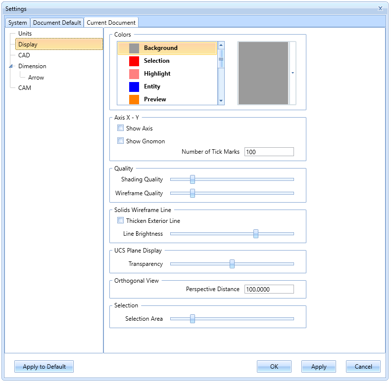
Click image for view larger image
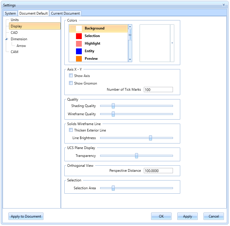
Click image for view larger image
Customize Ribbon
This option will allow you to fully customize the ribbon bar we introduced in V31. The modern, Ribbon-style user interface helped with discoverability, and organization, but the only drawback was for the users who prefer to customize their interface. At the time, the items in the ribbon were where they were, and could not be modified. Now, we allow you to adjust the contents of the tabs, create new tabs, and reorganize the existing commands anyway you see fit!
The Document Templates
The Document Templates allows users to save an entire file as a template. When the template is selected, that file is recreated as a new document. This functionality can be utilized in tons of different ways!
- Many companies offer a particular series of parts which each have slight variations. With the document templates, you can create the base geometry of the model, save the document as a template, and when the first variation has been completed, open the base geometry template so the next iteration is already halfway done!
- In some cases, the same stock is used for many different jobs. Simply import the fixture, create a job, set the Stock, Machine Setup location, Clearance values, and Work Offsets, and save the file as a template. Now, you can use that template anytime that stock is being used, and that work is already done!
- Some customers use a variety of Document styles for different situations. In the past you had two options for changing documents: Part Settings (the current document) and Default Settings (future documents). This meant that if you frequently used different settings, you were also frequently changing those settings back and forth. Now you can create document templates to handle all the cases you may want use and never need to touch the settings dialog again. Simply select one of your templates in the Backstage, and you're ready to go!
- In some cases, the same basic operations are used on nearly every part: A couple of Profiles, a couple of Pockets, and maybe a drilling operation or two. With the document templates, you can create a job with those features and operations, save the file as a template, and simply open the template, merge the appropriate file, and your job is almost done! Now all you have to do is associate geometry and the proper depths to each feature, compute, and the job is complete!
However you decide to utilize the Document Templates, the result is the same: Create fewer steps, and save yourself time!
CAD
New CAD Tree Options
In order to help reduce the size of saved BobCAD files, we introduce two ways to reduce the size of your CAD Tree and, as a result, the size of the resulting saved file. In our BobCAD-CAM V27 Release, we introduced the Solid Action Tree in order to aid in the design process. This was a huge help in the design process because you no longer had to start over, or undo steps until you got to the point that required a change. Since all of your steps were tracked in the CAD Tree, you could simply select that particular step and modify it. Of course, this solution created a brand new issue; since all of your steps were tracked and saved, the file size could increase exponentially. This can now be solved with:
CAD Tree Optimization
For the customers that utilize the CAD Tree to modify previous steps, we offer the ability to optimize the CAD Tree History. One thing we see a lot of is many incremental translations to get to a single result. The same thing goes for Rotate, Rotate 3D, and Delete. Instead of a single instance, many have been used in a row to achieve the result. Since every step is tracked and saved this causes a file size much larger than it needs to be. Now, you can simply optimize these functions and instead of tracking five separate instances of Translate to get from A to B, we simplify it to a single tracked instance. This can be applied to:
- Translate
- Rotate
- Rotate 3D
- Delete
In the example below, you can see a CAD Tree with some room for optimization, and the result of using the Optimize CAD Tree option. Notice the file size difference:
Delete CAD Tree History
For the customers who do not utilize the CAD Tree to modify previous steps, or for those who have files which have models that will no longer be modified, we offer the ability to completely delete the CAD Tree History. In this case, instead of attempting to optimize the steps in the CAD Tree so they can still be modified, the CAD Tree is completely deleted, greatly reducing the size of the saved file.
In the example below, you can see a CAD Tree which has been optimized, and the result of using the Delete Tree History option. Notice the file size difference:
CAM
General
The Default Parameter Templates
The Default Parameter Templates are designed to let you change the initial values listed for the options in the CAM Wizards. When programming in BobCAD-CAM, you move through the wizards to edit the default values of the Features and Operations to create the program as they see fit. In the past, many customers have requested that those default values be changed to something that suits them better. However, the problem has always been, for every person that wants the value changed to one thing, there another person that wants it changed to something else. (And don't forget about the guy that likes it just the way it is!) Now, in BobCAD-CAM V32, we introduce the Default Parameter Templates. Simply move through the wizards and change any values you want to remain constant. Then use the Save Defaults option to save those values to a template. Once saved, any time that template is used the features and operations that have been saved to it will have those same values.
The Job Templates
The Job Templates allow you to save an entire Job from the CAM Tree to use as a template for future projects. From speaking with our customers, we have found many shops using the same kind of setup, or setups, used over and over no matter the job. In this release, you can right-click on your job and select Save Job as Template. Once you name the job, and save the template, you're ready to use it. Next time you want to create a similar job, just select Job From Template instead of New Job. Then, simply pick the job type and the template you'd like to use and click OK, and your job is in the CAM Tree ready to go. Save as much or as little of the job as you want.
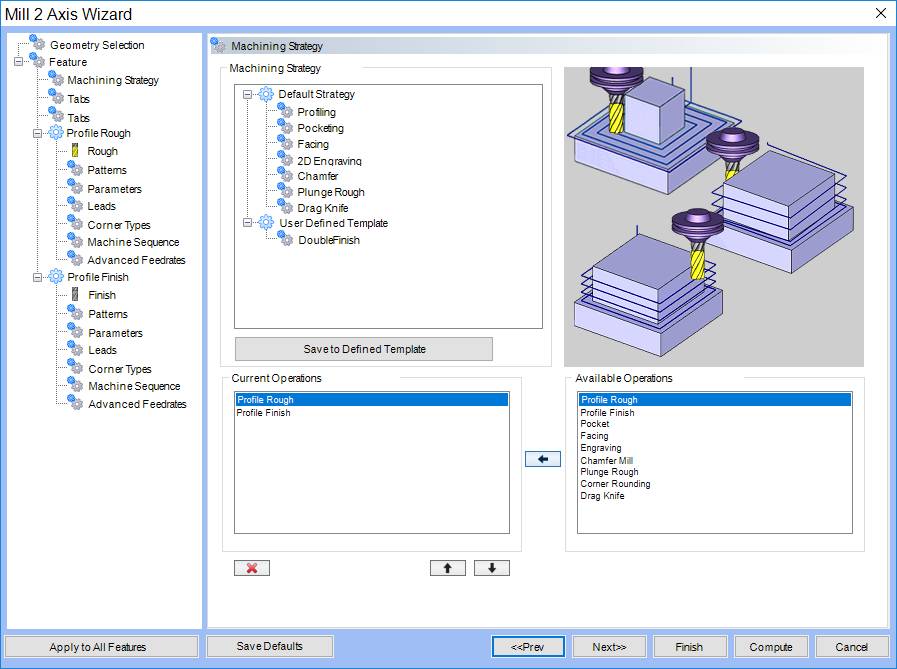
User Defined Machining Strategy Templates
The User Defined Machining Strategy Templates allow you to create custom Machining Strategy Templates that have all the operation settings saved with them. Our Machining Strategy Templates have been around for a while, but only a certain amount were available, and they were always loaded with the default settings. That meant that every time you used them, you would need to go through the entire feature, and all of its operations to update the settings to meet your needs. While you can now save operational defaults with the Default Parameter Templates mentioned above, the User Defined Machining Strategy Templates go beyond simple templates. Not only can you create as many as you need, but each template can have its own special operation settings saved in them. So the next time you load your template, that's all you need to do, because you already set the settings!
New Machining Order Dialog
The Machining Order Dialog allows you to quickly view the order the operations will be output, and reorder if necessary, and in this version, it's easier than ever to use. A Work Offset column has been added to provide additional information, and now drag and drop functionality is available. This means, instead of having to highlight an item in the list, and then use arrows to move it up and down the list, you can simply drag and drop it into position to reorder your operations!
In the images below, you'll notice, while an operation can dragged and dropped into position, icons will appear showing where it can, and cannot, be placed.
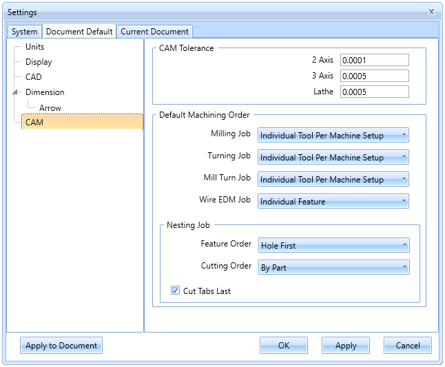
Default Machining Order Options in Settings
To go along with our improved Machining Order dialog, we now also offer a way to set machining order defaults! In the past, the machining order for every job defaulted to Individual Tool Per Machine Setup. While this is probably the most widely used option, it still meant if it wasn't the option you used, you would need to change it each time. Now in the Settings dialog, you can set a specific Machining Order to each type of job:
CAM Tree Flyouts
Here, at BobCAD-CAM, we are always trying to find ways to shave even more time off your part programming, and make your software more user friendly. In this version, we're introducing CAM Tree Flyouts. These allow you to double check some, and even edit other values by simply hovering over certain items in your CAM Tree. Our CAM Wizards make programming incredibly easy, but having to find an item in the CAM Tree, edit that item, and then move to the proper page just to find that value can still seem a little frustrating. We don't want you to have to go through that, you've had a hard enough day. With the CAM Tree Flyouts, hovering over an item will quickly give you access to information on the tools, stock, features, operations, and more! So now, even if you find yourself needing to update the speeds and feeds for the entire file, you'll be able to zip through and get it done with a smile.
In this release, the Tool Library has been updated to a more modern and intuitive interface. On top of that it now gives you the ability to add or modify tools without the need to open a new dialog, allows you to save additional copies of your library, and even has a powerful search/filter tool integrated into it.
The modern interface makes your tools and tool types easier to read, and the dialog itself can be resized:
With a single click, you can expand and collapse the tool parameters. This allows you to create and modify tools without the need to launch a separate dialog:
The new tool library also provides the means to group tools, and filter tools to make searching large libraries easier than ever before!
Drag and drop headers into the group area to group tools by column information:
The search filter can be a big help even in fairly small libraries. With the filter open, you can easily Select All of the tools in the current group, and then set conditions to show only the tools you are interested in seeing.
These improvements make the tool library a much more powerful tool, while at the same time, making it easier than ever to use!
Mill
Mill Express
Work Offset Patterns
BobCAD-CAM now allows you to output copies of entire machine setups, and allows you to specify different work offsets for each copy. While Toolpath Patterns have been offered in the past, and could be applied to Machine Setups, there was no way to output the same code with different work offsets. This could be a little frustrating when machining the same job on multiple locations on the table, because it meant you'd need to manually copy and paste the output, then adjust the work offset number on each copy by hand. Now, it's easy to create a Work Offset Pattern, set the work offset number to use, set the machining order, and even set a pattern type with distances so you can see how it would appear in simulation. The Work Offset Patterns allow you to view the toolpath in the graphics area, and to pattern the stock, fixtures, and workpiece in the simulation:

Blank Patterned Toolpath

Blank Patterned Toolpath
Pattern Stock
Pattern Fixture
Pattern Workpiece
Pattern Stock
Pattern Fixture
Pattern Workpiece
Pattern Stock
Pattern Fixture
Pattern Workpiece
Pattern Stock
Pattern Fixture
Pattern Workpiece
Fixtures
One of the big requests we've had from our customers, is to provide them the ability is to view the fixtures being used for the various machine setups, and to be able to check them for collisions. Now, BobCAD-CAM is proud to say, we are able to assign an individual fixture for each machine setup. And it's as easy as "1, 2, 3!" Simply right-click the fixture item under the associated machine setup, and select Re/Select, then pick the fixture geometry as it appears in the proper configuration, and select OK. This can be repeated for as many machine setups as necessary. Now, when you simulate, you will be able to see the selected fixture geometry, in the configuration it was selected in, for each setup!
Machine Setup - 1

Machine Setup - 2
Machine Setup - 3
Mill Facing Feature
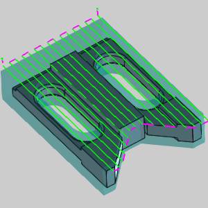
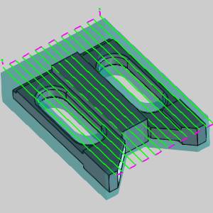
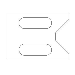
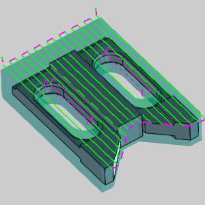
BobCAD-CAM now introduces another brand new feature: The Mill Facing feature! While we've always offered a Facing operation, it was accessed by creating a basic 2 Axis Feature. The only issue with this was that 2 Axis Features require geometry selection, and CAD models rarely contain geometry specifying the required stock shape. This meant the user now had to take the time to create that geometry. With the new Mill Facing feature, geometry selection isn't even necessary. Not only that, but if you select a Workpiece for the job, the new Mill Facing feature even sets the depth automatically, and gives you options on how to deal with the geometry! Choose from the default shape, a bounding box, or Keep Internal Loops.
| Part and Stock |
|
| Default |
Bounding Box |
Keep Internal Loops |
Feature Preview
Result
Feature Preview

Result
Feature Preview
Result
New Machine Sequence Options
BobCAD-CAM now offers new and improved sequencing options in order to offer lower cycle times. Two new, highly effective ways to maximize the efficiency of the sequence are now available. Along with our standard No Sorting, X/Y directions, and Closest options, a Custom Direction option you can define yourself has been added. We now even offer an Optimized sequence! With the Optimized option, each sequence is tested along with its own algorithm and the result which creates the shortest toolpath is the one you get!
Custom Direction
Optimized
Mill 3 Axis Pro
Trim Adaptive Depth Step Passes
Over the years, the Advanced Z Level Finish has come a long way. In this version, we offer a way to trim off the unnecessary portions of the Adaptive Depth of Cut to leave only what was needed. When we first offered the Adaptive Depth of Cut for the Advanced Z Level Finish, it was a huge help. Finally, areas of the part, whose steep angle caused large gaps in the toolpath, could be handled in a single operation by creating additional cuts on those levels. The only issue this caused, was the additional cuts went around the entire part. This meant if the surface that needed those additional cuts didn't go all the way around the part, there were now a bunch of unnecessary cuts on the other sides of the part. With the Trim Adaptive Depth Step Passes option, the rest of those unnecessary cuts are trimmed off, leaving the additional cuts only where they were intended.
Trim adaptive depth step passes
Trim adaptive depth step passes
Detect Stock Thicker Than
The new Detect Stock Thicker Than option for the Number of Intermediate Steps option in the Advanced Rough is designed to eliminate unnecessary intermediate steps. The Intermediate Steps option was a huge help when it came out. You could program your depth as deep as you dared, and set a particular number of intermediate steps. When your depth left large steps against the model, the intermediate steps would come back and focus only on those steps. It was a big time saver. The only issue, is that not all steps left against the model are created equal. Many of them weren't thick enough to cause a problem on the finish pass, but intermediate steps took those additional passes everywhere. Now, with the Detect Stock Thicker Than option, you finally have a way to specify steps that are not thick enough to worry about, and those will be ignored by the intermediate steps.
Num. of Intermediate Step
Num. of Intermediate Step
...Stock Thicker Than 0.000
Num. of Intermediate Step
...Stock Thicker Than 0.025
Advanced Allowance
An Advanced button is now available in the Allowance group of the Mill 3 Axis Pro operations which allows users to access the new Allowances dialog. This dialog provides the ability to specify particular surfaces/solids which should use a different allowance value than what has been assigned to the overall feature geometry. In the past, specifying different allowances for different surfaces required several different operations with specific boundaries assigned to each. The Allowances dialog simplifies all of this by providing you the means to simply add a geometry item, assign an allowance type, and then set the allowance amounts to use for each item. The dialog even lets you assign Part and Fixture geometry separately! In the images below, notice the fixture geometry selected. In this case we specify 0.2500 inches of allowance to use to keep the tool well clear of our fixture.
Fixture Geometry Surfaces
Mill 4 Axis Standard
Group improvements
When we introduced Groups in our V29 release, it brought some much needed organizational help to the CAM Tree. Now, Groups can also be utilized inside of Indexing System and Wrapping Groups! While Groups were a huge help for the overall machine setup, multiaxis users still ran into the same organizational issues with their Index Systems and Wrapping Groups. These users can now enjoy the same control and organization in any part of their job.
Mill 4 Axis Pro
4 Axis Advanced Rough and 4 Axis Advanced Finish Operations
Users familiar with our 4 Axis toolpaths can tell you, getting the perfect 4 Axis toolpath on complex parts could take a little work. Geometry selection needed to be precise. You would need to specify each surface to cut, you would need some edges to help define the pattern it should use, and because you were selecting individual surfaces, some gouge checking against particular surfaces might come into play. Finishing may need a couple different operations to achieve the desired result. Now, for the first time ever, you can pick the entire model and get the results you need, in a fraction of the time. The new 4 Axis Advanced Rough, automatically recognizes where the stock is, and avoids air cuts. The Advanced Finish automatically recognizes the walls in need of finishing, and tackles them precisely.
Specified Stock
4 Axis Advanced Rough
4 Axis Advanced Finish
Notice in the images above, the roughing toolpath ends where the stock ends, and the finish focuses only on the walls of the part model. Getting excellent 4 Axis results like these has never been easier!
Mill 5 Axis Pro
Toolpath smoothing
This option smooths sharp corners in the toolpath and replaces them with user defined splines. Smooth and steady wins the race in finishing parts, so it's not surprising that abrupt changes in direction aren't things programmers try to create in their toolpath, but they are still things that appear occasionally nonetheless. In the Advanced options for Surface Quality dialog, in the Surface paths page, you can now select the Smooth tool path option, set the Smoothing distance, and even specify a Detection angle to control when the splines should, and should not be used, and you can turn all those hard direction changes into nice smooth transitions.
Automatic arc - tool axis orientation
The Automatic arc lead option now allows you the ability to control the Tool axis orientation! The Automatic arc is a helpful tool, and for a while, the only thing lacking was the inability to control the orientation of the tool axis. In this new release, the Automatic arc option also allows you to control this with a Fixed, Tangential, or Tilted Tool axis orientation, to provide you with another level of control for an already powerful tool.
Feedrate for direct/spline links
One of the most important things in machining is the feedrate. In the beginning there was a single feedrate, which might not have been the best speed for every spot, but it was the only option. Slowly but surely more feedrate options became available: Feeds for your rapids, feeds for your leads, feeds based on contact point etc. Now, in our V32 release, you have another tool to pursue the perfect path: control over the feed rate of the Direct and Blend spline links!
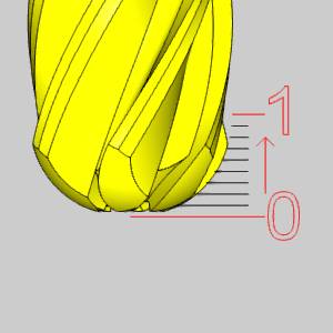
Side tilt by contact point
This feature provides a convenient, new tilting option for 5-axis machining. Sometimes the value an option is asking for, is not the value you know, just like you may know the date, but not what day of the week that would be. Having another way to describe what you want can be extremely helpful, and the side tilt option now offers that. When tilting relative to the cutting direction, you can now lilt the tool to a specific contact point, using a value representing height or an amount along the profile of the tool, instead of just entering an angle.
By Line Parameter
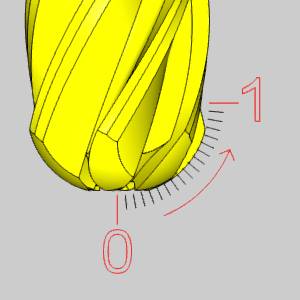
By Height
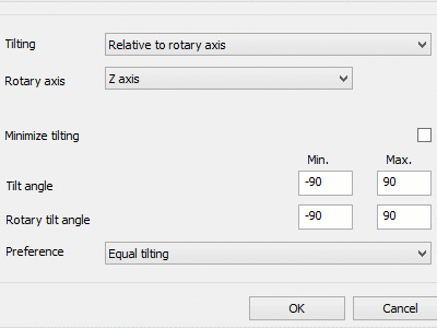
Minimize tilting
A new option has been added to the Gouge check page which allows you to help reduce fluctuations in the tilt of the tool, when you use the Automatic Tilt Tool strategy. Machining is all about part finishes, and to get a good finish, the smoother the moves, the better the finish. The Minimize tilting function is designed to smooth changes in the angle of the tool along the path, which helps to provide the best possible finish to your parts.
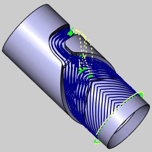
SWARF
Spiral cutting method
The SWARF toolpath type now has a Spiral method option in the Sorting group of the Multi Cuts page. A lot of time can be spent on parts getting the toolpath started in the right place, and using the right linking methods to make the finished part as clean as possible. Many things have been added to toolpaths in the past to help eliminate the evidence of linking moves, but if you're going to use a linking move, it's best to use one that leaves the part, moves to the next pass, and then returns to the part as smoothly as possible. When you leave the part though, you aren't cutting, and when you're not cutting, you're not making money. Now that the Spiral option is available for the SWARF toolpath, you can eliminate linking moves altogether by using a smooth spiral motion all the way through the toolpath.
Customize guide curve detection
When creating a Swarf machining feature without selecting Tilt lines, or Guide curves some intelligent decisions are made based on the surface selected for the feature. Unsurprisingly, if that geometry can be done many different ways, the result you get may not be the one you were expecting. Now, a Machining direction dialog is made available so you can enter the desired tool vector.

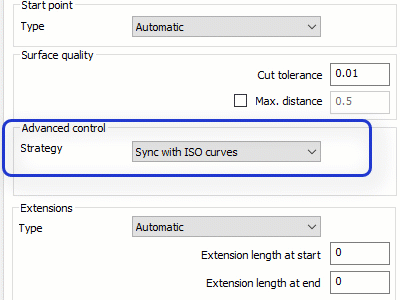
Sync with ISO curves
Another Strategy option that has been added to the Advanced control group of the Surface paths page is the Sync with ISO curves option, which allows you to utilize the curves of the surface itself as a guide. While there are many options to help you guide the tool for a swarf toolpath, there can be situations where the best course of action is to allow the surface structure to guide the tool. Now, with the Sync with ISO Curves option, you can do just that.
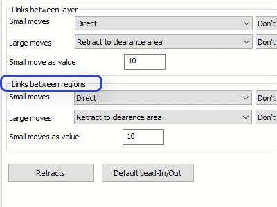
Links between regions
The Links between regions group has been added in the Link page to allow you to specify the type of movement to use between the different regions of toolpath. In previous versions, groups have been available to give you control over entry into, and exit from the toolpath, for dealing with gaps along the cuts, for links between the slices, and links between the layers, but there has never been an option for the links between regions. A large enough gap has always been considered a different area, and because of this, a clearance move has always used. With the new Links between regions group, these different areas of toolpath can be handled as regions, and now, you have access to all linking options you have for the rest of the groups in the Link page!
End Angle
In the Extensions group of the SWARF toolpath, you can now specify an end angle to use when exiting the toolpath. Having control over how the tool is leaving the part is just as important as how the tool enters the part. Now, just choosing the Start/End with angle option in the Extensions group of the Surface paths page, you can specify a End angle to use along with the Start angle.
Mill Turn
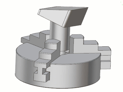
Chuck Jaws
For the first time ever, BobCAD-CAM offers a simple solution to quickly define chuck jaws in the user interface and view them in the simulation. Now, you can easily check chuck jaws for collisions, verify jaws opening and closing, spinning, and even syncing properly for part transfers!
Simulation
Next Feed Move
In the Simulation, there are 3 new buttons added that give you the ability to jump over rapid moves to get right to the feed moves. Since feed moves are the only moves that should be removing material, there are times when you just want to focus on the next feed move. Now, the Run, Step Backward, and Step Forward buttons have a drop-down to allow you to change to Prev Feed Move, Feed Move Run, and Next Feed Move respectively. Each time one of the buttons are pressed, the simulation will jump, or fast simulate, to the first encountered feed move type get you past the rapids, and right to the feeds.
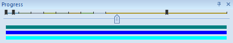
Move List Bookmarks
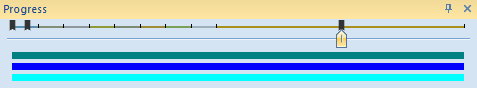
A new feature was added to Machine Simulator which allows you to add bookmarks to the move list with a simple double-click. Usually, when analyzing a simulation, there are portions of particular interest that the user returns to several times. Normally, this would be accomplished by remembering the operation number, and the block number, then moving to that operation, and going through the moves one by one. This can get pretty difficult when you have a few different places you want to keep returning to. With bookmarks, you can double-click the move in the move list to add a bookmark to the progress bar:
Click the bookmark in the progress bar to bring the simulation to that precise move. It's never been easier:
Keyboard Shortcuts All Isometric Views
For each isometric view, a shortcut key has been added to quickly rotate to that particular view. In the past only one isometric view was available, when the view cub was added, users had a way to move the other views by rotating the cube, and clicking on a particular corner. The only thing missing was the ability to utilize keyboard shortcuts to move to these views. In our V32 release, you can now use keyboard shortcuts for the:
- Upper Left Near Corner View
- Upper Right Near Corner View
- Bottom Right Near Corner View
- Bottom Left Near Corner View
- Upper Left Far Corner View
- Upper Right Far Corner View
- Bottom Right Far Corner View
- Bottom Left Far Corner View

Machine Coordinate System
A new coordinate system has been added to the Machine Simulator simulation area, called the Machine Coordinate System. This coordinate system is based on the machine definition, uses an internal detection algorithm for the main machine axis, and can be displayed on any corner of the simulation area. Some machines are created with coordinate systems that differ from the coordinate system shown in the simulation. This could be a little confusing when viewing the simulation, and in most cases, the best idea was to hide the Coordinate System to avoid confusion. In this release, the Machine Coordinate System has been added to the Graphics and Background page of the Machine Simulator Options dialog which allows you to view a coordinate system that is aligned with that of the machine.
Material Removal and Backplot modes: Setting retention
When switching between Material Removal mode, and Backplot mode, the state of the Initial Stock is now remembered. In previous versions the Initial Stock is always set to hidden when switching between these simulation modes. In our version V32 release the state of the Initial Stock will not be modified when changing from Material Removal mode, to Backplot mode, or vice versa.
Initial Stock in Material Removal mode:
Transparent
Initial Stock in Backplot mode:
Transparent
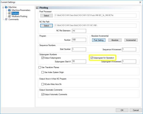
Posting
Subprograms
Subprogram for Operation
BobCAD now offers sub programs for individual operations. In the past, you could choose to output sub programs in the code, but BobCAD would try to make some assumptions in the output. A single depth profile, for instance, doesn't have multiple passes to create subprograms for, so why call a subprogram in the code? While this made sense in most cases, there are still situations where you would want that subprogram called, regardless of how many passes the operation has. Now, just by selecting the Subprogram for Operation check box in the Current Settings dialog, BobCAD will make no assumptions, and output a sub program for each and every operation.
In the table below, you can see how the Subprogram for Operation option changes the code for a basic, single pass Profile Finish.
|
|
Subprogram for Operation |
Subprogram for Operation |
|
|
N50 T4 M06
N51 G54
N52 G00 G90 X-1.3958 Y2.0625 S2383 M03
N53 G43 H4 D4 Z1. M08
N54 G00 Z0.2
N55 Z0.1
N56 G01 Z-0.25 F6.6738
N57 X0.7292 F13.3476
N58 Y-0.0625
N59 X-1.3958
N60 Y2.0625
N61 G00 Z0.2
N62 Z1.
N63 M09
N64 M05
N65 G90
N66 T1 M06
|
N09 T4 M06
N10 G54
N11 G00 G90 X-1.3958 Y2.0625 S2383 M03
N12 G43 H4 D4 Z1. M08
N13 M98 P16 (SUBPROGRAM CALL)
N14 M09
N15 M05
N16 G90
N17 T1 M06
O16 (SUBPROGRAM OF O100)
N01 G00 Z0.2
N02 Z0.1
N03 G01 Z-0.25 F6.6738
N04 X0.7292 F13.3476
N05 Y-0.0625
N06 X-1.3958
N07 Y2.0625
N08 G00 Z0.2
N09 Z1.
M99
|
|
|