CAD-CAM software can be a challenge to fully learn how to use for everything a CNC shop needs in order to program parts and output correct g-code programs efficiently. For as long as there has been CAD-CAM technologies, developers have faced the challenge of providing more and more functionality while continuing to keep these products easy to use. It hasn’t been easy. Ask any developer and they will tell you that the more features a CNC programming system has, the steeper the learning curves will be and the more technical support issues there will be. Yet without CAD-CAM, CNC shops simply cannot stay competitive and efficient.
The CAM Programming Challenge
A primary challenge of CAM has been keeping all of the necessary inputs together in a confined space while keeping the software easy to use and continue to streamline the workflow of CAM programming.
The General CAD-CAM Technology Workflow?
When you review the basic CAD-CAM programming workflow you will find that it goes something like this:
Import the part file or complete the design.
Create the material/stock for the job and origin.
Create a Machine Setup or Work Offset.
Setup the Material Type.
Setup Cutting Conditions, Tool Patterns and any Machining Parameters that apply.
Select the Post Processor Configuration.
Start adding machining features, drilling, roughing and finishing toolpaths.
Build the job in a CAM Tree Manager that allows you to edit the machining features.
Compute and generate all toolpaths.
Generate the G-Code Program.
Simulation.
RS 232 / DNC Send the program to the machine.
There is a lot of information that goes into the above list in order for CAD-CAM technology to really act smart and create efficient and effective programs for you. You have to input that information into the software. Otherwise you will often times get incorrect results and end up losing valuable time. So how has CAD-CAM been developed in order to keep it simple and make it so that nothing is left out?
The Solution: CAM Machining Wizards
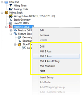
Wizards are used in software to properly set something up. In this case it includes a wizard for each drilling operation and all toolpath operations within the CAD-CAM system. In a CAD-CAM product the toolpath wizards should be easily accessible within a Job Tree – Manager so that the job remains organized. Here you can see an organized location within the Job Tree where all of the toolpath options are listed.
Once a machining strategy is selected the wizard will be launched to guide the operator through a proper sequence of steps for creating the toolpath. The wizard in BobCAD-CAM prompts the user to select associated geometry to use in the process. Once this is done the wizard advances to the Dynamic Machining Strategy™ box.
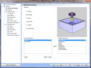 The first benefit is having all of your toolpath operations defined and organized into 2 Axis, 3 Axis, 4 Axis and 5 Axis categories. After having selected the associated CAD geometry for the machining, the user reaches the Dynamic Machining Strategy stage in BobCAD. In the picture here we have selected “Pocketing.” Then multiple operations can be loaded that are a part of that strategy and associated to the selected geometry. By choosing the “Next” button the wizard advances to the next box of the wizard. Once again, adding to the software intelligence and keeping things quick and easy for the operator. Advanced operators can jump to any section of the wizard just by clicking their mouse on the item in the wizard tree. When finished with these settings, the “Next” button will advance the wizard to the next screen.
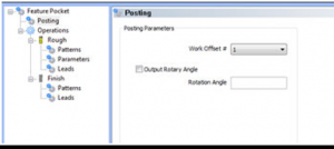
At this point the wizard will allow the operator to create an additional work offset if needed or a rotary angle if the program is for a 4th Axis.
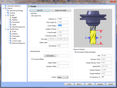
Now the wizard is allowing the operator to choose and control all of the aspects of the roughing tool. The Tool Crib and Holder database is accessible, tool data as well as speeds and feeds data can be used or customized by the operator. Once the roughing tool details are input the “Next” button is selected to advance.
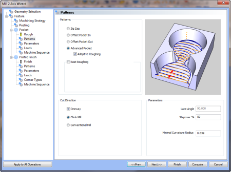
As the user advances through the wizard there is access to Patterns, Parameters, Leads and other aspects such as machining sequences and so forth. Different operations will have different screens that relate to the strategy be it pocketing, profiling or 3 axis roughing and finishing type strategies. Each wizard is relevant to what was selected as the strategy and any operations included through DMS functionality.
Here is the Patterns stage of the pocketing wizard below. This is where adaptive high speed options can be chosen for pocketing and more.
The wizard steps the user through the process of programming their part removing the guesswork. This level of CAD-CAM technology makes CNC machining automation valuable to manufacturing. To find out more about CAM Machining wizards contact BobCAD-CAM today at 877-262-2231.