Are you looking for a more simple way to cut shapes away from your solid models? The Extrude Cut function in BobCAD’s CAM software removes material from solid bodies by extruding closed wireframe chains or planar surface geometry to the specified distance and subtracts the result from any intersecting solid or surface bodies. When using a surface, the software automatically extracts the edges of the surface to use for the cut. Let’s take a look at how this works.
Pro Tip: Extrude Cut is applied to all intersecting bodies in the file, unless they are hidden using the View menu Blank function. Hiding a layer does not exclude the entities on that layer from being used in Extrude Cut.
For starters, you will find all of your solid editing tools inside the Solids menu in your CAD-CAM toolbar. Your Solids tab will house some primitive solid designs, standard boolean operations and your Extrude Cut feature.
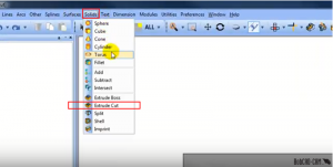
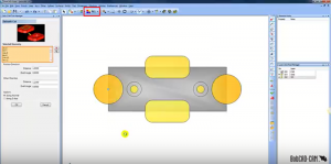
Start by selecting the Extrude Cut feature. Then go into your layers window and turn on the Wireframe boundaries you want to use to cut away from the model. To select by color, go into the ‘ALL’ option in your toolbar and pick a color. This will leave you with a preview of where your cuts will be made.
Subscribe to BobCAD-CAM's CNC Software Blog
Join your fellow manufacturers! Get BobCAD-CAM’s latest CAD-CAM articles straight to your inbox. Enter your email below:
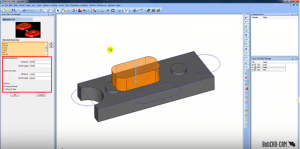
Next, go into the DATA CAM Tree Manager window and set the parameters that you want your model to be machined at. You will notice that there are a few different parameter options to set, here’s what they mean:
Distance- sets the distance of the extrusion from the selected geometry in the positive direction. You can use dynamic sketch handles or data entry to set this value. The snap increment applies to the distance value when using sketch handles.
Draft Angle- creates an angle along the edge of the extruded shape in the positive direction. This also applies to any internal shapes when you select more than one curve to extrude. This can be a positive or negative value.
Along Normal- the extrusion occurs parallel to the normal direction of the plane created by the selected curve.
Along Z-Axis- the extrusion direction is the Z-axis regardless of how the selected curve is oriented.
Once your parameters have been set to your liking, hit OK to compute. Your part is now programmed properly and ready to be machined, it’s that simple!
Thank you so much for reading this quick tutorial. If you want to try the Extrude Cut feature, download a free trial of our latest CAD-CAM HERE and give it a shot; see you next week!
You’re one click away from subscribing to BobCAD’s YouTube channel. Click the link below for tips, how-tos and much more!
Summary
Article Name
BobCAD's CNC Software Makes It Easy To Cut Shapes From Solid Models
Description
Are you looking for a more simple way to cut shapes away from your solid models? The Extrude Cut function in BobCAD’s CAM software removes material from solid bodies by extruding closed wireframe chains or planar surface geometry to the specified distance and subtracts the result from any intersecting solid or surface bodies.
Author
Michael A. Downss
BobCAD-CAM Software