Edit Toolpath - Trim and Relink
In this Topic ShowHide
Introduction
This topic explains the Parameters available when the Trim and Relink
Command Mode, which allows you to create
a trimming boundary to trim portions of the toolpath away, is used.
As explained in the Edit Toolpath Dialog
topic, most of the Edit Toolpath dialog remains the same, no matter which
Command Mode is being used. It is the Parameters of the Trim and Relink
Command Mode this topic focuses on, although, the Command Mode group,
Selected Toolpath Elements group and the Animation group can still be
revisited in this topic by expanding the drop down hot spots of the same
name.
To work through an example utilizing this function, see the Edit
Toolpath Example - Trim and Relink.
Actions
Parameters
Trim Boundary
 Click or Drag Window Pick - This
selection method allows you to select toolpath entities in several ways:
Click or Drag Window Pick - This
selection method allows you to select toolpath entities in several ways:
- Use a single click to select individual toolpath entities.
- Use Shift+Click on an entity to select an entire chain
of entities.
- Use a Window Selection method to drag a window around
a group of entities to select at once.
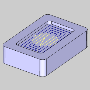
 Polygon Pick - This selection
method will allow you to define an area of selection by using multiple
single clicks to define a polygon. An example of this can be seen in the
image below. Click
here to see an example.
Polygon Pick - This selection
method will allow you to define an area of selection by using multiple
single clicks to define a polygon. An example of this can be seen in the
image below. Click
here to see an example.
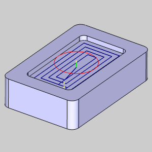
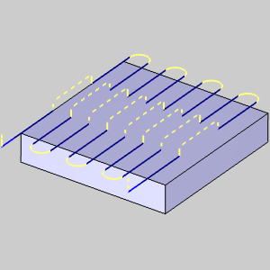
 Inside - Defines the area affected
by the command. With this check box selected, the toolpath elements within
the Trim Boundary will be trimmed and relinked.
Inside - Defines the area affected
by the command. With this check box selected, the toolpath elements within
the Trim Boundary will be trimmed and relinked.
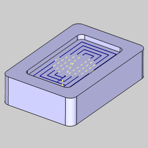
 Inside - Defines the area
affected by the command. With this check box cleared, the toolpath elements
outside of the Trim Boundary will be trimmed and relinked.
Inside - Defines the area
affected by the command. With this check box cleared, the toolpath elements
outside of the Trim Boundary will be trimmed and relinked.
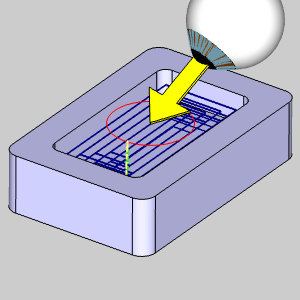
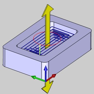
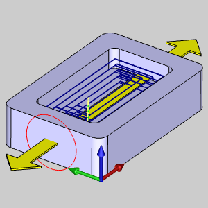
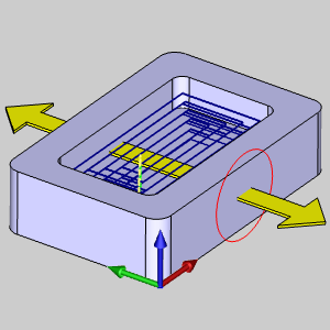
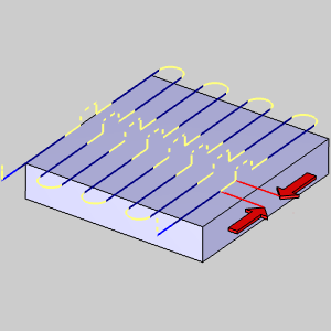
Usage -
determines how the Trim Boundary is used. This gives you the ability to
alter the direction the Trim Boundary is projected through the toolpath
elements. The available list items are:
Link
Link - dictates
the process of how to reconnect the trimmed segments of the selected toolpath
elements.
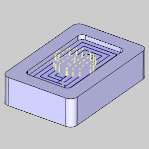
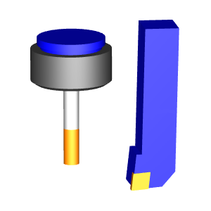
Retract and Plunge
- will retract from the exiting position in the trimmed
toolpath to a defined Z plane with a rapid move. This
will be followed by an X,Y rapid move to the next location,
at which point the tool will rapid down to the feed plane
above the next cut, and finally feed into the next cut
using the plunge feedrate. Click here
to see an example.
Retract
When
Retract / Plunge is chosen as the Link option, this value allows you to
set the Z plane height to be retracted to for the toolpath elements being
adjusted.
- Custom -
will allow you to set a specific Rapid Plane and Feed
Plane value to define the Retract / Plunge movements.
- Rapid
Plane - sets the custom Rapid Plane value
to be used.
- Absolute or
Incremental -
This toggle button determines how
this data is interpreted. Set this option to read
the Rapid Plane as either an Absolute or an Incremental
value.
- Feed
Plane - sets the custom Feed Plane value
to be used.
- Absolute or
Incremental -
This toggle button determines how
this data is interpreted. Set this option to read
the Feed Plane as either an Absolute or an Incremental
value.
-
Extension - With this checkbox cleared,
the ends of the selected toolpath elements will be left
as they are. The selected linking options will occur from
that position.
Extension - With this checkbox selected,
you will be creating a linear extension which is tangent
to the previous toolpath entity. The selected linking
options will occur from this new position.
Click
here to see an example of Extension.
- % of Tool or Absolute
- This toggle button determines how this
data is interpreted. Set this option to read the entered
extension as either a percentage of the tool diameter
or an absolute value.
Related Topics
Edit Toolpath Delete
Edit Toolpath Move
Edit Toolpath Replace
Edit Toolpath Break
Edit Toolpath Modify Attributes
Edit Toolpath Extend Cut
Move
Edit Toolpath Edit Tool Axis