Edit Toolpath Dialog
In this Topic ShowHide
Introduction
The purpose of the Edit Toolpath dialog is to give you the complete
freedom to modify the calculated toolpath by adding to, removing, and
modifying the existing toolpath elements. Although the bulk of the Edit
Toolpath dialog is the same, regardless of the command being used, each
command has a different set of Parameters to adjust. As such, all possible
commands share this same topic. The section on Parameters, however, is
divided by each possible command. For each of the available commands,
there is drop-down text to view the associated parameters. For each command,
there is also a link to an example you can follow along with to learn
to utilize that particular command.
WARNING!
The Toolpath Edit capability gives you complete
control over modifications of your toolpath. Be aware that there
is no guarantee that a modification made will be gouge free or create
unwanted motion at the motion. Please use caution and simulate your
results prior to running the program at the machine.
How to Use the Edit Toolpath Dialog
Once the Edit Toolpath dialog has launched, there are only a few key
steps to follow:
1 Set
the Command Mode.
2 Add
toolpath entities to the Selected Toolpath
Elements group by using either the Click
or Drag Window Pick, or the Polygon
Pick option.
NOTE: It is
not necessary to confirm the selection of toolpath entities. Add or remove
toolpath entities from the group at any point before executing the command.
3 Modify
the available options in the Parameters
group, to achieve the desired result.
4 Select
Execute to complete the Trim and
Relink command.
5 Use
the Animation options to check
the resulting tool movement.
After analyzing the resulting tool movement, you will either:
A Select
Undo to remove the previously
executed command and restore the toolpath to its former state.
Once Undo has been used you can either:
a Return
to step 1 to in order to achieve another result.
b Click
OK to finalize the current result
and exit the Edit Toolpath dialog box.
B Click
OK to finalize the current result
and exit the Edit Toolpath dialog box.
In the CAM Tree, the name of the edited operation is now in red font and
a  icon is added to show that the operation is locked
from being computed. This helps to ensure if a user uses the Compute All
option on the overall job, the edited operation will not accidentally
be returned to its original state. To return the operation to its original
state, right-click the operation and select Lock/Unlock Operation option.
icon is added to show that the operation is locked
from being computed. This helps to ensure if a user uses the Compute All
option on the overall job, the edited operation will not accidentally
be returned to its original state. To return the operation to its original
state, right-click the operation and select Lock/Unlock Operation option.
The icon disappears, and the operation is once again
able to be recomputed.
Actions
Command Mode
The Command Mode allows you to choose the
type of action you will perform on the selected toolpath elements.
Delete
- allows
you to delete toolpath entities and relink the toolpath.
Trim and
Relink - allows
you to create a trimming boundary to trim portions of the toolpath away.
Move -
allows you to alter the location of
the selected toolpath elements.
Replace -
allows you to draw in your own toolpath
and replace entities of the toolpath with this CAD geometry.
Break -
allows you to split toolpath entities into multiple segments.
Modify Attributes -
allows you to modify the feedrate, or feed type.
Extend Cut
Move - allows you to extend
the toolpath tangentially by a specified distance.
Edit Tool
Axis - gives you the option to modify the tool orientation
vector for a the selected toolpath elements.
This list shows the currently selected toolpath
entities.
 Click or Drag Window Pick - This
selection method allows you to select toolpath entities in several ways:
Click or Drag Window Pick - This
selection method allows you to select toolpath entities in several ways:
- Use a single click to select individual toolpath entities.
- Use Shift+Click on an entity to select an entire chain
of entities.
- Use a Window Selection method to drag a window around a
group of entities to select at once.
 Polygon Pick - This selection
method will allow you to define an area of selection by using multiple
single clicks to define a polygon. An example of this can be seen in the
image below. Click
here to see an example.
Polygon Pick - This selection
method will allow you to define an area of selection by using multiple
single clicks to define a polygon. An example of this can be seen in the
image below. Click
here to see an example.
 Point Pick - with this check box cleared toolpath points will not selectable.
 Point Pick - with this check box enabled, toolpath points can be selected,
by clicking near the end of a toolpath entity.
Point Pick - with this check box enabled, toolpath points can be selected,
by clicking near the end of a toolpath entity.
 Convert Selected Toolpath
to CAD Geometry - This button will create CAD geometry on the active
layer from the selected toolpath entities.
Convert Selected Toolpath
to CAD Geometry - This button will create CAD geometry on the active
layer from the selected toolpath entities.
NOTE: The Convert
Selected Toolpath to CAD Geometry option is currently limited to 100 entities
at a time.
Parameters
The available parameters vary greatly depending
on the currently selected command mode. To find out more about a particular
command modes available parameters, click on the associated link below
to jump to the topic outlining the particular parameter options.
Undo
This will remove the previously executed
commands.
Execute
This will perform the currently active command.
Redo
This will re-apply any commands that were
removed by the use of the undo button.
NOTE: The Undo
and Redo options only affect commands that were executed in the current
instance of the Toolpath Editor.
Animation
The animation will allow you view the tool in the graphics area in order
to verify the current tool movement. Controls are available to change
how the tool is viewed, adjust the speed of the animation, reset the animation,
along with the usual play, pause, fast back, step back, step forward and
fast forward.
Animation - with this check box
cleared, the view of the tool in the graphics area will be disabled.
Animation - with this check box
selected, the view of the tool in the graphics area will be enabled.
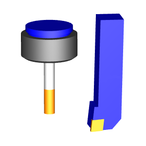
 Shaded - will show an opaque tool.
Click
here to see an example.
Shaded - will show an opaque tool.
Click
here to see an example.
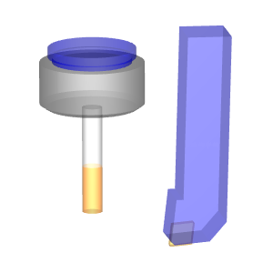
 Transparent - will show a transparent
tool. Click
here to see an example.
Transparent - will show a transparent
tool. Click
here to see an example.
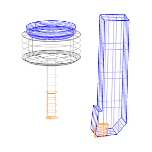
 Wireframe - will show the tool
as a wireframe. Click here to see an example.
Wireframe - will show the tool
as a wireframe. Click here to see an example.
Speed  -
This slider affects how quickly the tool goes through the toolpath
in the animation.
-
This slider affects how quickly the tool goes through the toolpath
in the animation.
 Reset - Sets the tool back to
the beginning of the toolpath.
Reset - Sets the tool back to
the beginning of the toolpath.
 Fast Back - Skips backwards from
the current position at 2X the setting of the speed slider.
Fast Back - Skips backwards from
the current position at 2X the setting of the speed slider.
 Step Back - Moves the tool backwards
along the toolpath by one entity.
Step Back - Moves the tool backwards
along the toolpath by one entity.
 Play - Starts the animation of
the tool moving through the toolpath.
Play - Starts the animation of
the tool moving through the toolpath.
 Pause - After pressing play, the
Play button changes to the Pause button to stop the tool at the current
Pause - After pressing play, the
Play button changes to the Pause button to stop the tool at the current
Toolpath Editor D
Animation
The animation will allow you view the tool in the graphics area in order
to verify the current tool movement. Controls are available to change
how the tool is viewed, adjust the speed of the animation, reset the animation,
along with the usual play, pause, fast back, step back, step forward and
fast forward.
Animation - with this check box
cleared, the view of the tool in the graphics area will be disabled.
Animation - with this check box
selected, the view of the tool in the graphics area will be enabled.
Shaded - will show an opaque tool.
Click
here to see an example.
Transparent - will show a transparent
tool. Click
here to see an example.
Wireframe - will show the tool
as a wireframe. Click here to see an example.
Speed -
This slider affects how quickly the tool goes through the toolpath
in the animation.
Reset - Sets the tool back to
the beginning of the toolpath.
Fast Back - Skips backwards from
the current position at 2X the setting of the speed slider.
Step Back - Moves the tool backwards
along the toolpath by one entity.
Play - Starts the animation of
the tool moving through the toolpath.
Pause - After pressing play, the
Play button changes to the Pause button to stop the tool at the current
position when pressed.
 Step Forward - Moves the tool
forwards along the toolpath by one entity.
Step Forward - Moves the tool
forwards along the toolpath by one entity.
 Fast Forward - Skips forwards
from the current position at 2X the setting of the speed slider.
Fast Forward - Skips forwards
from the current position at 2X the setting of the speed slider.
Related Topics
Edit
Toolpath Example - Delete
Edit
Toolpath Example - Trim and Relink
Edit
Toolpath Example - Move
Edit
Toolpath Example - Replace
Edit
Toolpath Example - Break
Edit
Toolpath Example - Modify Attributes
Edit
Toolpath Example - Extend Cut Move
Edit
Toolpath Example - Edit Tool Axis