Tech Tuesday is a weekly blog that addresses some of the most common questions and concerns that I hear throughout the previous week from users of BobCAD-CAM software. Both customers and future customers are more than welcome to leave a comment on what they would like to see covered for the following Tech Tuesday. Enjoy!
You know G-code and use your machine’s canned cycles to tackle your daily programming jobs. Why would you need or want a CAD-CAM system for your Mill Turn machine?
Toolpath cycles and options that speed up programming, faster and easier than conversational or hand programming.
Turning Cycles
Most CNC lathes have canned cycles for standard roughing and finishing on the OD, Face and ID of the part. What does CAD CAM offer that’s different or better?
Roughing
Choose from a standard pattern or offset style. Pick the best roughing cycle for the stock to achieve the highest removal rate.
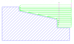
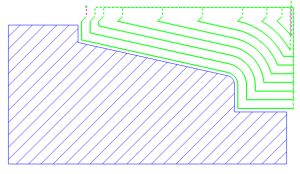
2-way roughing cycles.
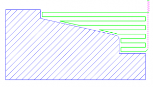
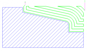
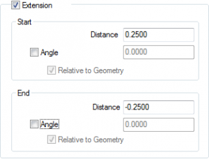
When programming your parts with BobCAD, you can extend or trim your toolpath using a simple dialog. Just check it on and use a positive number to extend & a negative number to trim the toolpath.
Finishing
The type of material, tooling and the experience you have in front of your machine will guide you to the best practices for finishing. Speed up your programming time using one of BobCAD’s finishing cycles. Choose from 4 finishing patterns that support downcutting for vertical walls
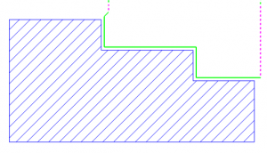
Finishing Continuous- Cutting in a single continuous direction.
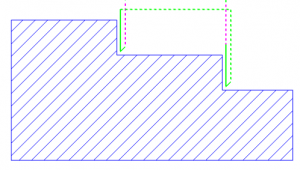
Finishing Face Only- Downcutting only on vertical walls/faces.
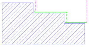
Finishing Turn Only- Single direction cutting on the Turn diameter only.
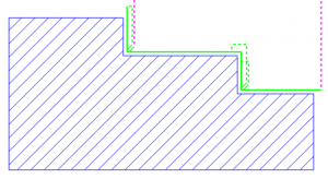
Finishing Both- Both turn and face down cutting
Operation Stock
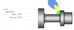
BobCAD’s new toolpath cycles and options are providing more control where and how roughing & finishing cycles are generated. Operation stock is one of the tools you can use to contain toolpath. BobCAD will keep track of your stock condition as you remove material and users can trim toolpath to the in-process stock.
Sure BobCAD has upped its game when it comes to turning cycles, but let’s take a look at the milling cycles the Mill Turn package offers to speed up programming.
Face Milling
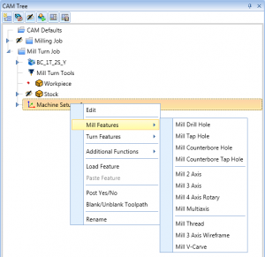 Programming bolt patterns, tapping cycles, pockets, profiles & engraving is extremely easy to do with BobCAD’s Mill Turn software. The same features we offer for Milling are found in our Mill Turn software. New Job Tree Templates allow you to capture and resue CAM Tree jobs. Very fast workflow, just select your geometry compute and go.
 If you’re tapping holes or thread milling, use the thread library to store and load thread types and their settings. BobCAD comes preloaded with standard and common threads, coupled with the ability to add to and edit the library to meet your needs.
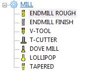
BobCAD’s tool library also comes loaded with standard tooling that can be added to match the tooling you use in your shop. We offer 7 tool-type categories and the ability to set up custom form tools by user selected geometry.
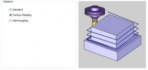
BobCAD offers 3 profile patterns to aid in the roughing and finishing of part profiles. Choose a standard profile to walk the tool around the part contour. Or choose contour ramping to ramp the tool while it cuts. Have extra stock that needs more than one pass? That’s what side roughing is for which you tell how much stock is left and how many passes.
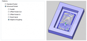
BobCAD now offers 10 types of pocketing patterns. Giving you lots of choices for the best strategy for the part geometry and material you are working with. Maybe you’ll choose an offset pocket for softer materials and the adaptive roughing for harder materials. The choice is yours and you have lots of options.
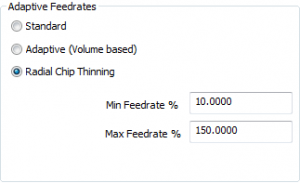
Adaptive feedrates have also been added to the pocketing toolpaths to speed up and slow down the feedrate based on two advanced feedrate calculations.
OD Milling
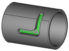
All the toolpath options you have for face milling, you’ll also have access to for OD Milling. To program your live tool Lathe using C axis only, users will use wrapping groups.
Subscribe to BobCAD-CAM's Tech Tuesday Blog
Join your fellow machinists. Get the latest Tech Tuesday CAD-CAM articles sent to your inbox. Enter your email below:
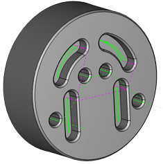
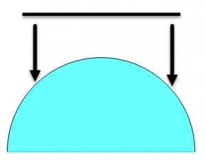
Once you’ve loaded a wrapping group into your CAM tree, all machining features loaded below it will be wrapped to the user-defined diameter. BobCAD supports working with either wrapped geometry or unwrapped geometry. This allows programmers to work off the solid model supplied from the customer or to create their own layout using 2D geometry.
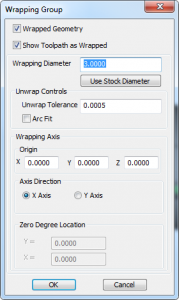
Wrapping groups do not use Y axis, they are for C axis programming only. Wrapping groups will keep your tool pointed to the axis of rotation.
Great for J slots, clearance pockets, engraving and other geometry features found on the OD of your part.
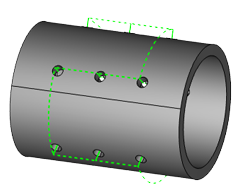
Cross Drilling
Drill, Tap and Counterbore cycles support cross drilling. One of the 3 hole-types that BobCAD supports. The advantage here is BobCAD does all the heavy lifting by automatically selecting cross holes based off your model selection. Using cross drilling, users can pick the hole cycle they want to process, select the solid model and BobCAD will automatically find the cross holes, removing any holes that do not intersect with the axis of rotation. This is another huge time saver that typically gets overlooked by new users.
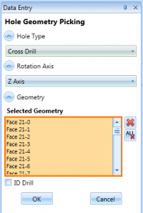
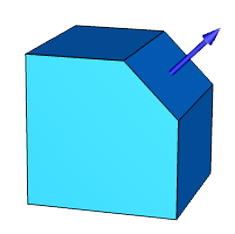
Index System
What if you are running a Mill Turn with a Y Axis, how does BobCAD handle that? Index systems. They are used to align your tool to the surfaces or features you want to machine.
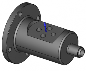
Take this example, where we need to machine a pocket then drill & thread mill some ports. We used the index system to align the geometry features to our tooling. You can pick a surface or a UCS to establish an index system. Once you’ve set up the index system, all of your 2D and 3D toolpaths can be used on your part’s features.
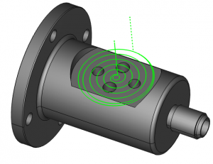
It’s important to understand you can use both 2D machining features and 3D machining features.
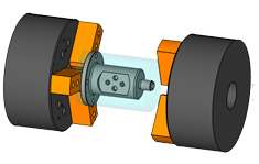
Multiple Spindles
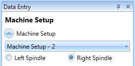 Programming your main or sub-spindle is easy to set up and execute with BobCAD’s Mill Turn package. We use independent machine setups (work offsets) for each spindle. All the machining features found below that setup will be programming features for that spindle.
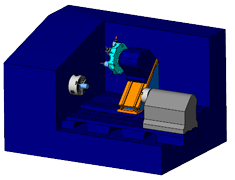
Machine Simulation
A fully loaded Lathe turret is extremely difficult to visualize where collisions might be. It’s like programming in the dark. Turn the light on using machine simulation and graphically verify & check for collisions with your tool holder, turret, adapters, chuck spindle, and other machine components.
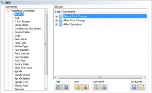
Mill Turn machines can be complicated, requiring special program blocks to control all of the machine components as your part is running.
Use BobCAD’s MDI programming for:
-Macro Programming Blocks
-Procedural Syncing
-Sub-spindle & turret location
-Probing cycles
-In process inspection
-Part transfers and more
MDI allows users to create, store and reuse programming blocks (G & M Codes).
Load user-defined codes and comments before your tool change, after your tool change or after the operation.

Depending on your Mill Turn configuration and controller, you may want or need to swap posting modes to produce the best possible part in the shortest cycle time. BobCAD supports posting long-hand code, Y axis code or polar coordinates.
Post processors will produce:
-Separate move cycles
-Canned cycles
-Tool changes and offsets
-C Axis
-Y Axis
-Polar coordinates
That’s about all the time we have for today. Thank you for reading another Tech Tuesday; see you next week!
You’re one click away from subscribing to BobCAD’s YouTube channel. Click the link below for tips, how-tos and much more!