Every shop has experienced the negative impact of a machine collision, tool break, or untimely part gouge. These can have serious financial impacts on a business by way of repair & tool replacement costs and machine downtown.
With complex machining, any one of these errors can easily happen. Even with simple machine operations, these can still occur if proper care isn’t taken. Errors could be caused by any number of reasons including improper tool selection, fixture set-up, or the more likely cause is a simple programming error.
Shops that use BobCAD-CAM software to develop their CNC programs can fall back on the software’s simulators to help eliminate these types of productivity killers. As CAD-CAM software has advanced, so has the user’s ability to realistically visualize the machining process.
It’s the simulator’s job to identify potential programming errors in an off-line setting, before the g-code is ever created and transferred over to the CNC machine. In the last 10 years, simulators have become so successful at identifying costly machining mistakes that shops, small and large, that use them consider simulators vital to maintaining their profitability.
CAD-CAM System Simulations: Break pixels, not $100,000 machines.
Integrated directly into the CAD-CAM software, simulators are no longer reserved for the expensive systems. Affordability combined with advancements in computer hardware and graphics capabilities have made simulators accessible to job shops of all sizes.
What features should have you implementing simulators into your machining process today?
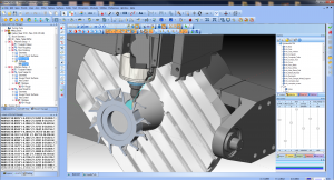
1. View and proof cut paths from any angle
2. Set machine travel limits and detect over travels
3. Check for part errors – including machine, tool, and tool holder collisions
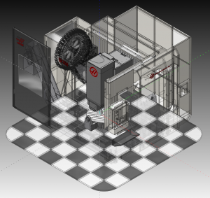
4. Utilize you machine’s kinematics to visually see your machine tool in action
5. See exactly how the part will look cut on your machine at any point during the machining process in a virtual environment
6. Set up an unlimited amount of virtual machines that match the machines in your shop
7. Assign transparency levels of the simulated machines for enhanced part viewing ability
8. Accurately calculate cycle times
9. Use dynamic viewing functionality for better inspections
10. Identify machine-part deviations to know where tools were unable to machine within the associated operations.
The big picture benefits include less time wasted on machine errors, fewer parts scrapped, and general peace of mind knowing you have more control over your machining process.
Identifying the Machined Part Deviation
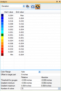
In setting up the simulation, the user can define deviation tolerances with color assignments. When the operator runs the simulation, any areas where the tool left excess material will be clearly identified. This works for both milling toolpaths and drilling operations.
In addition to color identifiers on the virtual part, the CAD-CAM software will list any deviations in a customizable deviation analysis tab. With two ways to identify deviations, the user can easily determine ideal surface finishes and any problems associated with the current tool selection and size.
Picture: Shades of blue were assigned varying levels of deviation in the picture insert.
Advanced CNC Machine Simulation
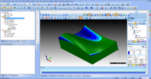
The simulation feature is designed to provide realistic virtual machining, which includes importing the kinematic features of the actual machine in the user’s shop. Machine creation begins with defining each element of the machine to be used, such as the linear and rotary axis attributes. Next, parameter values are established, including the moving direction and limits. This is essential data for the CAD-CAM program to generate accurate g-code for the NC programs. For each element, geometry files (.stl) are added to define what appears in the simulation window.
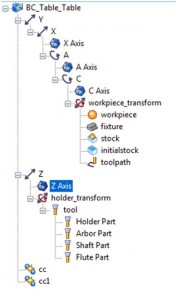
Above is an example structure of a machine tree and machine elements. The machine is the base by which each machine element is defined.
Once the machine data is entered, the user can save the machine for future use and machine simulations are now possible.
In the BobCAD-CAM CNC Software, machine simulations also include what are known as “Dynamic Elements.” These are elements that can change with each NC program.

The Workpiece Transform element contains the first set of dynamic elements in the tree. This transform includes the toolpath, initial stock, stock fixture, and workpiece. Generally, the user isn’t required to define geometry for each of these items because they are defined by the program being created. This holds true for the Holder Transform elements. BobCAD-CAM CNC Software automatically generates these dynamic elements in the tree when a new machine is created (except when using user defined).
In the BobCAD-CAM Professional Machine Simulation version, the geometry for the holder element in simulation is automatically defined using the assigned tool holder from the milling wizards.
One thing’s for certain, CNC machine simulation is NOT a fluff feature. Its empowering designers and operators with the tools necessary to increase workflow efficiency, reduce machining errors, and most importantly, increase profitability.
For more information on implementing a CAD-CAM software with machine simulation into your CNC business, call BobCAD-CAM, Inc. at 877-262-2231 or 727-442-3554.
Download a FREE demo of BobCAD-CAM with CNC machine simulation to test the power of simulation today! Click HERE to download
Here are other CAD-CAM related links that you may find interesting:


Summary
Article Name10 REASONS TO USE CAD-CAM SYSTEM SIMULATIONS FOR CNC PROGRAMS
DescriptionCNC Machine simulations within BobCAD-CAM software is helping shops increase efficiency and reduce costs associated with costly programming errors. Find out how using BobCAD-CAM to run realistic simulations as part of your machining process can save you time and money.
Author
Nick Erickson | BobCAD-CAM