by Chris Corbell
CNC Machining & The Need for Toolpath
It’s no mystery that CNC businesses have to maintain a high efficiency level when it comes to machining parts. This is where programming automation can make a big difference in a shop’s bottom line. The word “Toolpath” is a CAD/CAM related term that is basically a series of coordinate locations that a cutting tool will follow in the machining process. Toolpath is traditionally divided into two categories: Roughing and Finishing. A roughing toolpath is generally used in the CAD/CAM cnc programming phase for removing the most amount of material possible, as accurately and as efficiently as possible. Finishing toolpath comes after roughing and essentially “finishes” the cutting process removing the last amount of material on the machine to complete the machining process. CAD/CAM software toolpath has been under development for the last 20 years becoming smarter, faster and more robust in terms of what can be done with it by CAD/CAM developers.
Even in today’s fast-paced, competitive manufacturing industry, cnc businesses are still learning about it and shopping for toolpath capabilities that make better sense of their machines and provide better ways to accommodate the needs of shops that want an edge in part-making. Without toolpath there is no CAD/CAM benefit – it’s that simple. So what are the advantages of CAD/CAM toolpath? To answer this we should break it all down by complexity level.
2 Axis Machine Toolpaths
Shops that do cnc machine work all have one thing in common when it comes to toolpath: they all need “2 Axis Toolpath” machining capabilities. Let’s look at some of these toolpaths and their benefits.
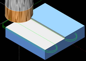 Face Milling Toolpath: This type of milling operation is very common. Benefit can be achieved when there is a constant engagement between the cutter and the material. CAD/CAM software helps automate the programming process by allowing the user to dictate what the toolpath result will be. This includes options for cutting direction, what distance the programmer will specify for moving off and back onto the workpiece, tool starting position, and additional parameters that include the step over percentage for the cutting tool. These options can include single or multiple cutting (roughing) passes along with depth controls.
Other important Face milling controls will determine how the toolpath linking will output. An example is the ability to change from a direct traditional type link or an arc link as seen in the illustration.
Profile Milling Toolpath: This type of milling operation allows you to machine around the profile geometry of a part. Typically this will be used in three process situations; 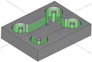 Roughing/Semi-roughing, Semi-finishing and finishing. You can also see this in what is known as “Super-finishing” where high speed toolpaths are employed. An example of this process in finishing would be REST milling where the milling of remaining stock is performed. In some cases roughing and finishing operations are performed on different machines where dedicated cutting tools are used for each operation – whatever the case, profile milling operations can be easily performed with CAD/CAM software where benefits can be achieved.
There are several ways that profile toolpath can be used in the machining process:
Profile – Semi Finish
Profile – single level Side Rough
Profile Side Rough – Roughing Multi-Depth
Profile-Finish – Side Rough REST
Profile milling can easily be achieved with a CAD/CAM system that offers this strategy with multiple options that include compensation setting, pattern options for standard profiling, contour ramping and side roughing options. This will include roughing and/or finishing tools, toolpath lead-in and out options, and more.
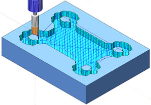
Pocket Milling Toolpath: This type of milling is very common for clearing out a volume of material. CAD/CAM software allows you to set up the parameters of the toolpath based off of the part model and tooling for the job as well as other factors. Typically the software will either recognize the pocket geometry where “feature recognition” is available or simply allow the programmer to pick the regions of the part model that require pocket milling. Computer Aided Manufacturing (CAM) software will allow the programmer to set the parameters of the pocketing strategy through data input and selection options that are all geared at pocketing. Modern CAD/CAM systems will provide a CAM Job Tree Manager which gives the operator access to all 2D machining operations/strategies. This allows the programmer to choose the operation and open the feature dialog box or launch a machining wizard to step them through the process. The “wizard” procedure is more desirable as it removes the guesswork from having to figure out where everything is.
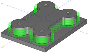
These will often include Patterns such as zig-zag, machining from the center outward or outside inward, climb or conventional milling options, an angle for the toolpath to be created as well as even offer high speed pocketing toolpath to be created. Other parameters will include cutting depth selection and input options and access to roughing and finishing tools from a user-definable database of tools, tool holders and more. Here are some examples:
High Speed Contained-Roughing
Open Wall Advanced Pocket Roughing
High Speed Core-Roughing
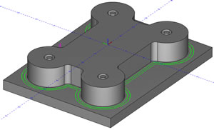
High Speed Core-Bottom Finish
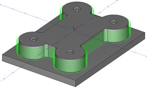
In recent years the development of high speed toolpaths has made a positive impact on cnc machining. These high speed toolpaths do away with the traditional right turn, left turn stop and go approach that beats on tools, materials and your machine. These new toolpaths introduce a much cleaner, efficient and speed enabling approach that can vastly reduce cycle times, extend tool life and promote the health of the machine all in one.
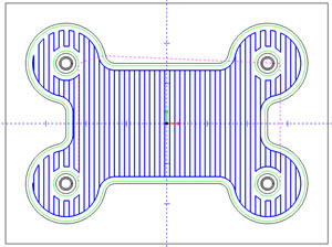
Traditional Pocket Toolpath
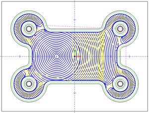
High Speed Pocket Toolpath
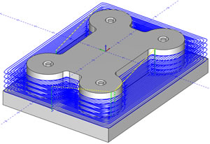
The basic theory behind high speed toolpath is that there is a constant engagement during cutting, constant chip load, a minimal amount of feed rate loss due to the stop and go movements in traditional toolpath and the ability to increase cutting speeds due to the circular (trochoidal) machining motion. Additional intelligence can be developed into high speed toolpath that takes into consideration areas that have already been machined as well as automatic tool repositioning. This is where the software knows where the tool has been during cutting in relation to the part model and creates a finishing toolpath for the finishing tool all in one operation. This can almost be considered a REST (re-machining) operation within the pocketing operation to finish what the first tool did not cut.
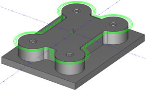
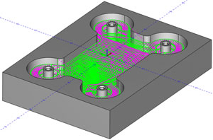
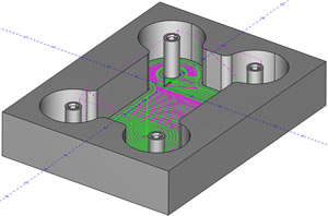
Here is a high speed pocket roughing toolpath operation with a REST finishing toolpath operation that can be used with the BobCAD-CAM 3 Axis PRO-Level software:
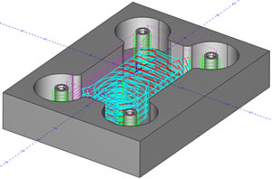
A CAD/CAM system should offer a variety of toolpath styles for different machining scenarios and one that offers high speed toolpaths is a real plus in becoming more efficient and profitable.
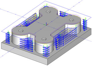
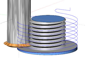
Plunge Rough-Milling Toolpath: Plunge roughing can also be known as “Drill-Roughing” depending on the CAD/CAM product. This style of machining operation can be used as a fast way to remove a large amount of material. Rather than a traditional pocket style the tool plunges down into the material and retracts to step over and plunge again as the method of cutting. The tool makes a series of overlapping plunge moves to remove one cylindrical plug of material at a time.
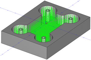
Plunge Roughing Toolpath
Plunge Roughing Simulation
The increased rigidity of a Z axis move allows the tool to machine a larger cross section without changing the feed rate. Traditional cutters can be used for this machining operation as well as special plunging tools.
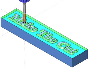
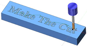
Engraving Toolpath: Engraving toolpath allows the operator to using v-carving tools or other cutters to machine letters, designs made with profile geometry and more. From machining part numbers into parts to elaborate custom type woodworking, engraving toolpath is used.
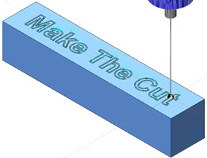
Outline Letter Engraving
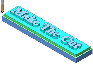
Raised Letter Engraving
V-Carving is also a form of 3D engraving. This type of toolpath will allow you to create raised letters through combining a v-cutting tool with an endmill cutting tool.
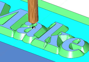
V-Carving also allows for the creation of toolpath in what is known as “X-Cornering” or “Center-Line” engraving. This is where you can achieve a sort of chiseled look to the letters. The toolpath is created for a v-cutting or tapered cutting tool. The CAM software allows you to use vectorized fonts and creates a toolpath based on the center of the geometry.

A lot can be done with CAD/CAM software for creating different engraving scenarios. The point is…Toolpath is created based off of the operators input for each of these examples.
Thread Milling Toolpath: Some advantages of thread milling, as compared to single-point cutting or taps and dies are faster cycle times, less tool breakage, and that a left- or right-hand thread can be created with the same tool. CAM software will ask for variable input data such as whether the thread will be created “bottom up” or “top down” as well as if it is an inside thread or outside thread. Then there are the thread parameters such as the thread diameter, height, pitch and the number of threads per revolution. Once the depth information is input, generally CAM software allows the operator to select or choose a lead-in and a lead-out for the toolpath.
Machine Toolpath Wizards such as the ones in BobCAD-CAM software are very useful as they step the operator through programming the toolpath, removing the guesswork and streamlining the process.
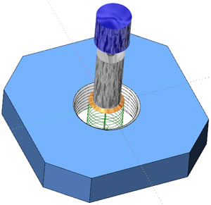
Inside Thread Milling
Outside Thread Milling
The toolpath is achieved either using helical interpolation (which is circular interpolation in one plane (typically X and Y) along with simultaneous linear interpolation along the Z axis. Manual programming of this is not practical and is why CAD/CAM is the way to go here.
Improving Efficiency & Beyond
These are the general 2D Toolpaths of CAD/CAM programming software along with examples of each. CAD/CAM software will provide a variety of 2D toolpath for your parts and automate the entire process. Basically the operator will determine which 2D strategy to use along with tooling etc. The software takes the geometry or part model and offers faster solutions to get to the machining stage quicker and more efficiently. We recommend using a CAD/CAM system that uses “Wizards” for the toolpath stage. CAD/CAM will also offer simulation capabilities to simulate and analyze toolpaths, reducing the potential for costly mistakes and wasted time.
For more information on implementing 2D Toolpath and CAD/CAM software into your business call us at 877-262-2231 or 727-442-3554. Click here for a free demo.