 CAD-CAM software has everything to do with modern CNC machine programming and plays a critical role in the future success of manufacturing at a global level. Manufacturers are continuously looking for solutions to improving CNC automation that are efficient, safe and take the most profitable route to making parts. When it comes to CAM programming, the programmer/operator can look at a part model and determine the right machining strategies that will lead to a finished part and then heavily relies on CAD-CAM software capabilities to get the right results. This is where a Quality CAD-CAM system that offers the widest variety of 2D & 3D cutting strategies becomes the winner. Determining the best 2D vs. 3D cutting toolpath strategies is easier than you might think, yet still commands a certain level of training to fully understand how the operations work and the results that can be achieved by using them.
Look for cost affective CAD-CAM Software that gives you:
– 2D Machine Toolpath Strategies
– 3D Machine Toolpath Strategies
– Simulation
– NC Editor
– Customizable Post Processing
– Excellent Training
Understanding 2D CAD-CAM Programming
2D Toolpaths are typically based on wire frame. Generally, if you are drawing a part from scratch you use points lines and arc to create your geometry. Once you’ve drawn the features you need to machine in the part you’ll apply 2D tool paths for machining.
2D Wire Frame types used in CAM include:
Points
Lines
ARCS
Other Shapes
Splines
These types of geometries can be used for drawing profiles to be machined and more that include boundary geometry that is used to contain toolpath into a specific region of a part model.
2D CAM Programming Operations:
Drilling
Facing
Profile
Pocketing
Thread Milling
Engraving
Chamfer
Corner Rounding
Plunge Rough
These machining operations are available through Dynamic Machine Strategy™ functionality where the user can use multiple operations for individual CAD features. This streamlines creating the machining operations and simplifies the process as the user can get more done in less CAM moves. Note that if you’ve imported a file or choose to create a solid model of your part you can use surface edges as boundaries for 2D tool paths, and you can use surface edges to define the depth of your toolpaths.
Understanding 3D CAD-CAM Programming
3D drawings mostly are based off of wire frame boundaries that are used to create surfaces or solids. There are Surfacing / Solids features that do not require any wire fame, they use user input as an example, primitive solids shapes. Also you can use surface edges to create additional surfaces or solids.
3D geometry types and functionality used to create Surfaces include:
Rectangular Plane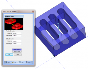
Circular Plane
Planar
Extrude Curve
Extrude Surface
Revolve
Sweep
Cross Section
Skin
Offset
3 Edge
4 Edge
Multi-Sided Patch
Fillet
Swung
Ruled
3D primitive Solids include:
Sphere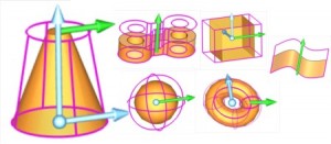
Cube
Code
Cylinder
Torus
Fillet
Primitive solids are used in combination with solid Boolean editing features to create solid models. 
3D Surface/Solid Editing Features:
Add
Subtract
Intersect
Split
Shell
Extrude Boss
Extrude Cut
Extend
Intersection Curves
Untrim Surface
Break Surface
Section
Scale
Now that you have a 3D surface or solid you can apply 3D tool path to them. 3D toolpath cut where and to the surfaces you have selected. So unlike 2D tool path where you define a boundary and depth, 3D toolpaths are applied to the model directly and where they cut and how deep are based on the surface or solid directly.
3D Toolpaths Surface that are Solid Based: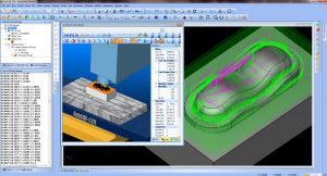
Z Level Rough
Z Level Finish
Planar
Spiral
Radial
Plunge Rough
Advanced Rough
Flatlands
Equidistant offset
Pencil
Advanced Planar
Project Curves
Advanced Z Level Finish
3D Toolpaths that are Surface Based Only: 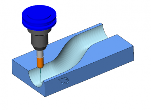
Parallel Cuts
Cuts Along Curve
Morph Between 2 Curves (Flowline style machine toolpath)
Parallel To Multiple Curves
Project Curves
Morph Between 2 Surfaces
Parallel To Surface
Cutting options you use in 3D toolpaths effect where toolpath is created. Toolpaths are created based off the model surfaces you’ve selected, and depending on the cutting options for that toolpath like the stock for finish, DOC, boundary, operational stock , surfaces you’ve select to avoid ( check surfaces ) effect where material s left over or targeted for cleanup. 2D CAD-CAM will always have a place in machine shops for CNC machine programming. 3D CAD-CAM allows shops to efficiently manufacture complex geometry and handle harder jobs with much success.
To learn more about how CAD-CAM software can positively impact your shop, contact BobCAD-CAM today at 877-262-2231 or 727-442-3554.
Try a FREE CAD-CAM software demo HERE