Tech Tuesday is a weekly blog that addresses some of the most common questions and concerns that I hear throughout the previous week from users of BobCAD-CAM software. Both customers and future customers are more than welcome to leave a comment on what they would like to see covered for the following Tech Tuesday. Enjoy!
In today’s manufacturing world more and more shops are adding 5 Axis capabilities. Keeping up with challenging part geometries and shorter lead times may be the driving factor for some, others just think it’s really cool. The technology is less expensive and more widespread than ever before. Let’s take a look at a sample project and some of the toolpath used in 5 Axis.
When it comes to 5 Axis machining, there are 3 main types of machine configurations. Let’s take a look at what those are.
Table Table Configuration
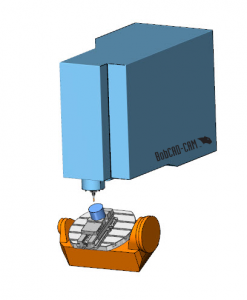
This is where both of the rotation axes are found on the table. This type of configuration is very common, mainly due to the fact that you can “bolt on” a trunnion table. Allowing you to convert your shop’s 3 Axis Mill into a 5 Axis Mill.
Head Table Configuration
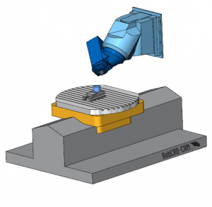
This is where 1 rotation axis is found on the head of the machine and the other is found on the table of the machine.
Head Head Configuration
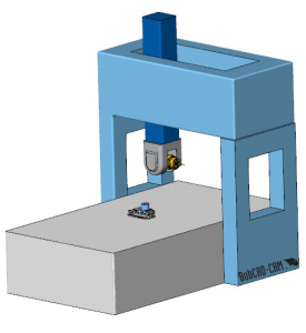
This is where both rotation axes are found on the head of the machine.
Subscribe to BobCAD-CAM's Tech Tuesday Blog
Join your fellow machinists. Get the latest Tech Tuesday CAD-CAM articles sent to your inbox. Enter your email below:
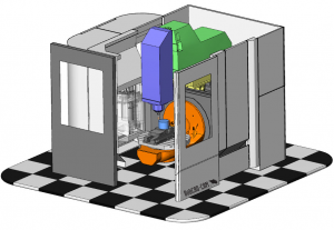
BobCAD’s CAM software supports all three of these 5 Axis machine configurations. In our example, we are using a DMG Mori DMU 50.
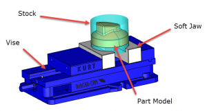
In this 5 Axis example, we are using a Kurt vise with soft jaws holding cylindrical stock. There are lots of work holding options and it’s common to use a riser purchased or made to move your stock geometry up off the table to gain clearance.
So now that we understand how were are holding the part, let’s talk about toolpaths. Using the BobCAD-CAM 5 Axis Mill Professional, there are many toolpath options to choose from.
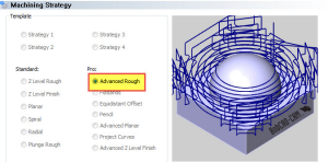
As most of you know, the go-to roughing toolpath is Advanced Rough. This powerhouse of a toolpath will do a great job removing the bulk of the material using an adaptive toolpath pattern. Just because we are using a 5 Axis machine doesn’t mean we need to rough our part in 5 Axis.
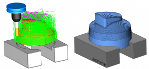
*Backplot and simulated stock removal
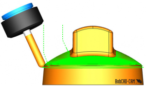
Now that we have the bulk of the material removed, let’s look at finishing some of these surfaces. For the top of our model, we want to use a surface based toolpath.
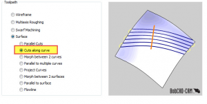
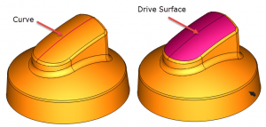
In this example we used cut’s along a curve. This toolpath is based on 2 geometry selections. One is the curve, the second being the drive surface.
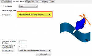
Using surface based toolpaths, users have control over the tilt of the tool. There are many tilt control options and in this example, we used ‘be tilted relative to cutting direction’. Users can adjust the lead angle to cutting direction and the tilt angle at the side of cutting direction. This gives you more control over how the tool will engage with the material.
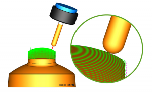
As users make an adjustment to tilt, optimizing their toolpaths, they can backplot to visualize their changes.
Cuts along a curve toolpath creates a perpendicular pattern to the drive curve along the drive surface.
An often used feature of BobCAD’s surface based toolpaths is the extend and trim option. This tool is used to extend the toolpath tangentially off the edges of your drive surface.
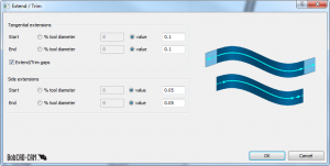
This feature can be used to extend toolpath at the edges of the drive surface and the sides of the drive surface.
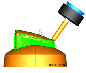
Now that we have our top surface finished, let’s look at the wall surfaces. In this example, we used morph between 2 curves.
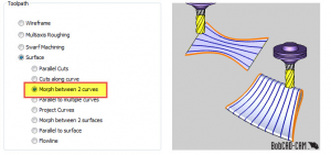
This morphed or “blended” toolpath will do a great job finishing these walls. Morph/Blended style toolpaths are great for thick to thin surfaces.
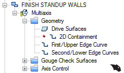
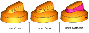
This toolpath is based on 2 selections, one the 2 curves the toolpath with morph between and the drive surface(s) the toolpath will be driven along.
Now that we have our selection complete, let’s take a look at the tilt strategy used in this example. We are using Tilted with fixed angle to axis. We use this option to tilt the tool away from the vertical surface to give us clearance for the tool tip. This way we are driving our toolpath with the ball on the tool instead of the side flutes of the cutter.
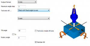
We are using our Z-Axis as our Tilt reference and set up the tilt angle to 35 degrees. We’ve also checked maintain tilt, this way the tool contact with our drive surface will be at a consistent angle while cutting these surfaces.
Now that we’ve finished the walls, let’s take a look at the top of the domed surface. In this example, we used another morph between 2 curves toolpath. Again providing a great finish and blending the toolpath between the top irregular profile to the circular profile. We also used a Tilted with fixed angle to axis strategy to control the tilt angle. Thank you for reading another Tech Tuesday; see you next week.
Start your Test Drive.
Have questions? Call us at 877-838-1275.
You’re one click away from subscribing to BobCAD’s YouTube channel. Click the link below for tips, how-tos and much more!
To see if BobCAD’s Mill Turn software is right for your shop,
Summary
Article Name
3 Main Machine Configurations in 5 Axis Mill Professional CAM Software
Description
In today’s manufacturing world more and more shops are adding 5 Axis capabilities. Keeping up with challenging part geometries and shorter lead times may be the driving factor for some, others just think it’s really cool. The technology is less expensive and more widespread than ever before. Let’s take a look a sample project and some of the toolpath used in 5 Axis.
Author
Michael A. Downss
BobCAD-CAM Software