Tech Tuesday is a weekly blog that addresses some of the most common questions and concerns that I hear throughout the previous week from users of BobCAD-CAM software. Both customers and future customers are more than welcome to leave a comment on what they would like to see covered for the following Tech Tuesday. Enjoy!
This article will navigate you through your CAD-CAM’s stock wizard and the 6 stock types you will be using. Those stock types include the following: rectangular, cylindrical, wireframe, solid model, STL file and revolved. At the beginning of every job, you will need to run the stock wizard, establishing your material or additional stock as needed. Let’s take a look at the 6 different stock types and how to use them!
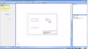
In some instances, it may become necessary to select your workpiece. Your workpiece is the part model that you are working with. The reason you would select your workpiece is for simulation and the drilling options that we have in the software. In this case, we don’t need to select a workpiece because we are working with a DXF file.
Wireframe Stock
Since it isn’t necessary to select a workpiece in wireframe, we are now presented with our 6 different stock types. Once we select our stock type, advance to the next screen. Depending on what kind of stock you are using, there are different questions you will need to answer.
Note: Users can adjust stock color, transparency or blank stock by right-clicking on the stock in the CAM Tree and selecting the corresponding option.
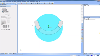
To select the wireframe on your screen, select ‘pick geometry’ and click the lines & arcs that make up the stock. Once we select all the way around the part, hit space to lock it in. The spacebar is a shortcut for ‘OK’.
The next steps we will take to set up our stock are establishing the top of stock and height values. This allows you to adjust where the top of the stock is located relative to the selected geometry. Height will change the overall thickness of your stock. While picking on the top of the stock, you can either enter numeric values or pick off of the geometry.
Cylindrical Stock
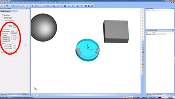
This stock type we are going to explore is a cylindrical part. Let’s go back into our stock wizard like we did before, select cylindrical stock and hit ‘next’.
The first thing we will want to pay attention to is the bounding box option. Using the bounding box option, BobCAD will calculate your cylindrical stock size based on your part’s geometry.
What the bounding box does is it looks at the geometry and calculates where it thinks the stock should be, based on a minimum/ maximum (aka, the stock doesn’t encompass all of the part). That will have to do with how the box is calculated.
The next choice you have is a bounding cylinder. A bounding cylinder calculates the cylinder in a different formula, so if you find that the bounding box doesn’t get all your geometry, then this is your alternative function.
Now, as you move through your geometry options, you will see you have a few different ones. ‘Auto from workspace’ means the software surveys the geometry for you, or you can use the ‘pick’ option. The ‘pick’ option is really useful for when you have multiple bodies on the screen. Just highlight the object(s) you want to isolate and then hit your spacebar to confirm.
The next thing we can do with this particular stock is we can edit the values of the diameter and height under ‘stock definition’. It’s worth noting that as you add height, it will increase in size from the top of the job down. If you want to change it so you can increase the height from the top going up, you have some offset options in the lower left corner of the CAM Tree.
Rectangular Stock
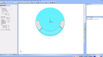
In this next part file, we will utilize wireframe geometry again with this irregular shape. Using the bounding box, the geometry found is the minimum/ maximum of the part. If we were to use the pick geometry option and reselect our profile, we get a rectangle all the way around the stock, even though it’s irregular.
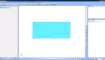
If you want the exact irregularly shaped profile as your stock geometry, go into stock definition and choose wireframe. This will deliver your irregular stock, fitted to all the curves of your part.
If you want to change where the top of the stock is, you can either pick off of the screen or entering numeric values in the ‘top of stock’ and ‘height’ options in the CAM Tree.
Solid Model Stock
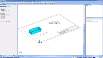
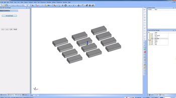
This part file is for our users that have parts in either multiple vices or they have a fixture plate with multiple bodies of stock. The image below is a fixture plate with pins, clamps and multiple bodies that need to be machined.
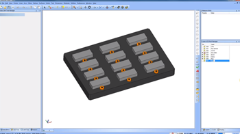
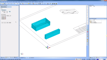
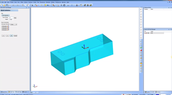
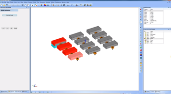
As we set this job with multiple bodies of stock, we want to utilize the solid model stock type and then select our solid models individually by clicking on them. After you hit the spacebar, you will see your models look like the image below.
Unfortunately, in solid model stock, users cannot add stock to all the solids. Instead, you have to draw it to size. Additionally, if you want to simulate all the stock bodies on your fixture plate, select ‘pick model’ and then select the multiple bodies that represent the stock you are working with.
STL Stock
Generally, I’m going to use this option for in-process stock when I have run a simulation & then I want to use that simulated stock from one job to another job. What sets it apart is you will grab the STL stock option from a directory and then set the units to either millimeters or inches. Other than that, it is similar to the solid model stock in terms of setup.
Revolved Stock
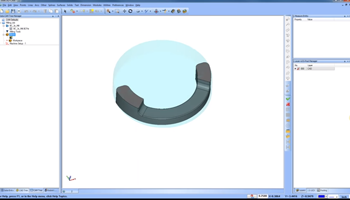
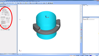
Users will want to utilize this option for stock that is round. To begin, we will select ‘pick geometry’, click on our part and then hit the spacebar.
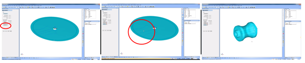
People often get confused while using revolved stock due to the stock orientation on the screen showing that the ‘Z’ is pointing up (left image). To change this, select ‘Z direction’ in the CAM Tree, clicking the line you want it to revolve around (middle image). As you can see in the right image, we now have the orientation revolving around the X Axis, giving us our revolved stock. Thank you so much for reading another Tech Tuesday, see you next week!
Start your Test Drive.
Have questions? Call us at 877-838-1275.
You’re one click away from subscribing to BobCAD’s YouTube channel. Click the link below for tips, how-tos and much more!
To see if BobCAD’s Mill Turn software is right for your shop,
Summary
Article Name
Tech Tuesday: 6 Stock Types In Your CAM Software Stock Wizard
Description
This article will navigate you through the stock wizard and the 6 stock types that include the following: rectangular, cylindrical, wireframe, solid model, STL file and revolved.
Author
Michael A. Downss
BobCAD-CAM Software