Tech Tuesday is a weekly blog that addresses some of the most common questions and concerns that I hear throughout the previous week from users of BobCAD-CAM software. Both customers and future customers are more than welcome to leave a comment on what they would like to see covered for the following Tech Tuesday. Enjoy!
Using machine simulation for 4 and 5 axis part programming offers huge benefits to developing collision-free toolpath. In order to take advantage of this feature, you’ll need to build a machine within your BobCAD CNC software.
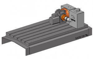
When building a machine, you’re defining your machine’s “kinematics”, which is really just a fancy word for how the machine moves and its configuration. You’ll also want to add geometry, like the machine base & rotary products to use in collision checking groups.
Over the last weekend, I’ve spent a few hours working for a rotary tilt sample and here’s what I found to be important & the mistakes to avoid when building this machine.
1. Where is the Machine’s Zero?
Now, this may seem like an obvious step, but for me, it was a huge mistake that cost me a lot of time and frustration. Before you start anything, you have to understand where the machine zero will be for your exact build. This is important because the “offsets” you’ll use; the machine components all need to be based on this one location.
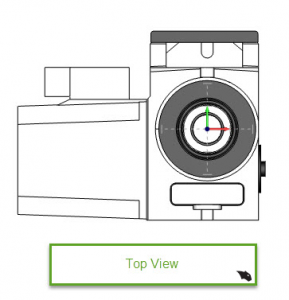
In our example, the zero will be on the face of the HA5C collet.
This mistake cost me a lot of time and frustration. When I first built this setup, I had the zero at the centerline of the A axis. This caused all kinds of issues in latter steps, so don’t fall for the same thing. Understand where the machine zero will be for your configuration before you do anything else!
2. Machine Component Models
Most machine OEM will provide you with models & if they don’t, they will have a print with dimensions so you can create your own. In our example, we are using the supplied models from HAAS; they are good like that!
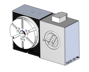
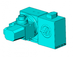
We are using the HRT210.
And HA5C.
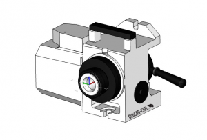
What we need to do at this point is to align the 2 models so that match our setup. When I opened the X_T models from HAAS, both of the rotary product’s zero was at the face and on centerline.
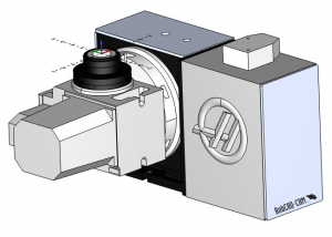
Starting with the HA5C, we need to rotate the model so it’s facing straight up as it would be attached to our HRT210, making sure to keep the face of the collet at zero.
Next, we need to align the HRT210 to the HA5C as they would be on the machine. There is an adapter plate that HAAS offers which I did not have any information on at the time of this build. So, I moved the HRT210 into position so that both the HA5C and the HRT210’s rotary axis intersected.
Pro Tip: To work with both rotary products in the same file, I used file merge. This way the HRT210 and the HA5C file are in one CAD file. I also made sure each rotary product was on its own layer. Doing so made it easy to select/view each rotary product independently. After the file merges, I saved the file as a BBCD, as not to alter the original X_T files.
With this example, I needed to move the HRT210 down 5 inches in Z and over 2.25 In X. This translation aligns both rotary products. It also provides us with the offset distance from the face of the HA5C to the HRT210 axis of rotation. We’ll use this information in future steps.
3. Saving STL Files
Now that we have both rotary products relative to each other with a known offset value, we are ready to save out our STL files. When building a machine, we use STL files for the machine components. We will “add geometry” when editing the machine’s definition.
When saving the machine components, the start of the file name must match the name of the machine you are building.
When saving the rotary products, you’ll have to save 2 files for reach rotary product. One for the part of the rotary product that rotates, the other being based on the rotary product that doesn’t rotate.
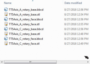
Pro Tip: Be sure to save each component out as an STL and BBCD file. This way, if you need to make any changes, you have the sold models to work off of.
For more information about the naming of the models, click here.
Subscribe to BobCAD-CAM's Tech Tuesday Blog
Join your fellow machinists. Get the latest Tech Tuesday CAD-CAM articles sent to your inbox. Enter your email below:
4. Building the Machine
Ok, now that we have our models saved as STL file, we are ready to start building our machine.
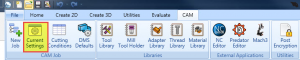
From the CAM menu, we will go to where it says current settings.
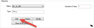
From there, we will click Add to create a new machine.
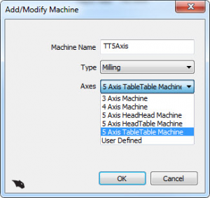
We will name our machine TT5Axis (Tech Tuesday 5 Axis) and choose a 5 axis TableTable machine setup. Using one of the supplied temples makes it easy to build your own machine without having to start from scratch.
Why are we using a 5 Axis TableTable machine? It’s because both rotary products are attached and happen on the table of the machine.
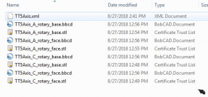
After we create the machine, a folder will be made with the machine name in the following directory: C:\BobCAD-CAM Data\BobCAD-CAM V31\MachSim\TT5Axis
In this folder is an XML file which is used for all the setting of the machine. What we want to do at this point is copy all our STL files for our rotary products to this folder.
5. Adding Geometry
Our next step is to start adding geometry. So, how do you do this and where do you add the geometry? In our example, we need to add both rotary products to our TT5Axis Mill.
Because we have 2 rotary products, don’t we just add the rotary base and rotary face models to the machine definition? No. My first run through setting up this machine, I added both of the rotary face and rotary base STL files to the A axis and C axis. The problem when doing this was both the rotary face and the rotary-based end up in rotation when that axis rotates. The solution was super simple and I was kicking myself when I found the answer. The rotary base models are added to the X axis, which is where they are mounted on the real machine. Simple, right?
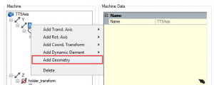
To add geometry to the X axis, just right-click on the X axis and choose add geometry.
Let’s add the A axis rotary base to the X axis.
Next, we will add the C axis rotary-based to the A axis.
Now that we have both of the rotary-based models added, let’s add the C axis rotary face to the C axis.
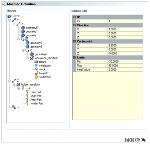
Then we will add the A axis rotary face geometry to the A axis )after we’ve added the geometry at the offset value for the relative location of the A axis to the machine zero). In this case, the absolute distance the A axis is away from the machine zero. With our example, we know it’s -5 in Z and 2.25 in X.
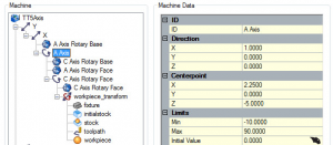
We will add these offsets for the Centerpoint input field.
At the same time, we can add some limits to the rotation of the rotary axis. In our example, I am using a -10 minimum and a 90 maximum.
6. Testing
At this point, our machine is set up and ready for some testing. I’ve created a simple cylinder with some drill holes for testing. It’s important to understand the machine zero is at the face of the C axis. So, when we set up our job, make sure to put the origin at the bottom of the stock.
Using a test file, we can check our limits in X & Y and rotary directions. There you have it, thank you again for reading another Tech Tuesday; see you next week!
Start your Test Drive.
Have questions? Call us at 877-838-1275.
You’re one click away from subscribing to BobCAD’s YouTube channel. Click the link below for tips, how-tos and much more!
To see if BobCAD’s Mill Turn software is right for your shop,
Summary
Article Name
Tech Tuesday: Build A 5 Axis Rotary Tilt In Your CAM Software
Description
Using machine simulation for 4 and 5 axis part programming offers huge benefits to developing collision-free toolpath. In order to take advantage of this feature, you’ll need to build a machine within your BobCAD CNC software.
Author
Michael A. Downss
BobCAD-CAM Software