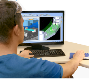
 A CAD-CAM demo walk-through is an efficient way to evaluate the advantages and benefits of any CNC programming system. This is why BobCAD-CAM has simplified the process of evaluating their CAD-CAM products without ever having to leave their free downloadable demo. The purpose of the Demo Walk-through that has been added to the BobCAD-CAM V27 software is to allow prospects and customers to easily access examples showing full CAD design and CAM usage within the BobCAD software.
Four large buttons appear at the bottom of the screen when opening an example part, allowing users to view the CAD, CAM, Simulation, and Posting at the click of a button! Each part that is supplied in the software has a full written tutorial and video walk-through of exactly how these parts were created using the BobCAD software, and will guide the user through recreating these examples himself. This document describes what features of the software are highlighted in the new Demo Walk-through parts. We will be releasing 3 files with the first release of the Demo Walk-through; a Mill Express part, a Mill 3 Axis Standard part, and a Mill 3 Axis Pro part.
Mill Express CAD-CAM Part
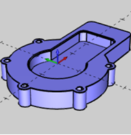
This part shows the creation of a basic solid with several drill holes and a pocket.
Mill Express CAD Design Highlights
– Using the Shape Library
– Creating Hole Patterns
– Creating and managing CAD layers
– Deleting geometry
– Using 2D Boolean to add wireframe chains
– Using Quick Trim
– Using Extrude Boss
– Using Extrude Cut
– Creating chamfers with Solid Fillet
Mill Express CAM Machining Highlights
– Creating a milling job, stock, and setting the machining origin
– Selecting a stock material to determine automatic feeds and speeds calculations
– Creating 2 Axis features for Facing
– Creating 2 Axis features for Profiling
– Creating 2 Axis features for Pocketing
– Creating 2 Axis features for Chamfering
– Setting the start points for 2 Axis operations
– Creating Mill Drill Hole features
– Using the CAM Wizards to guide you through creating machining features
– Selecting tools from the Tool Library and Tool Crib
– Tips for easier viewing of computed toolpaths
– Simulating the program
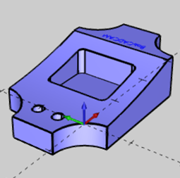
The V27 CAD-CAM Mill 3 Axis Part
This part shows the creation of a solid model that requires 3 axis machining techniques. This way the user can learn how easy it is to create a 3D model for applying 3 Axis CAM toolpaths.
3D Mill CAD Design Highlights:
– Creating wireframe with the Shape Library
– Creating and managing CAD layers
– Using Arc Coordinates
– How to modify entity attributes
– Utilizing UCS planes for CAD creation
– Using Extrude Curve
– Utilizing CAD layers to aid in geometry selection
– Using Extrude Cut
– Creating text
The Mill 3 Axis CAM Machining Highlights
– Creating a milling job, stock, and setting the machining origin
– Selecting a stock material to determine automatic feeds and speeds calculations
– Creating Mill 2 Axis features for profiling, pocketing, and engraving
– Reversing the chain direction for 2-axis operations
– Creating Mill Drill Hole features
– Creating Mill 3 Axis features
– Assigning boundaries to limit 3-axis toolpaths
– Using loop selection to select 3D chains from a solid model
– Modifying the CAD model to exclude features from the toolpath calculation
– Using the CAM Wizards to guide you through creating machining features
– Selecting tools from the Tool Library and Tool Crib
– Utilizing CAD layers to hide and show geometry
– Using Pick options to set Feature parameters
– Tips for easier viewing of computed toolpaths
– Simulating the program
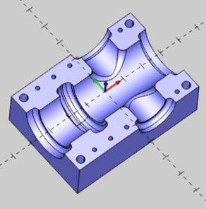
The Mill CAD-CAM 3 Axis Pro Part
This part displays the ease of creation of a more complex model that offers several of the common machining situations encountered when cutting any complex 3D model.
The CAD Design Highlights of the Mill 3 Axis Pro
– Utilizing UCS planes for CAD creation
– Creating solid primitives
– Wireframe creation
– Extrude Boss
– Subtracting solids
– Solid Filleting
– Hole Patterns
– Extrude Cut
The 3 Axis Mill Pro CAM Machining Highlights
This part of the demo walk-through teaches the user how to machine the part that they just designed.
– Creating a milling job, stock, and defining the machining origin
– Selecting a stock material to determine automatic speeds and feeds calculations
– Using CAM Wizards to guide you through easily creating 9 milling operations
– Utilizing a 3 Axis feature to rough and finish the part with operations from the 3 Axis Pro module
– Creating an Advanced Rough operation to rough the cavity
– Using a second Advanced Rough operation for Rest Roughing
– Tips for easier viewing of computed toolpath
– Simulating the roughing operations
– Editing a feature and adding finishing operations to the Machining Strategy
– Advanced Planar toolpath for shallow area cutting
– Advanced Z Level Finish for steep area cutting
– Pencil milling to finish the internal corners
– Simulating the finishing operations
– Performing Deviation Analysis
– Creating Mill Drill features and defining operation parameters
– Center Drill and Drill multiple hole sizes
– Simulating the finished program
This documentation comes with the latest free demo download that BobCAD-CAM offers to give you a well rounded evaluation of our CAD-CAM software.
Download a FREE V27 CAD-CAM Demo today! Click HERE