 Working with CNC machines doesn’t have to be complicated. CAD-CAM software was created to streamline the CNC programming process with ease of use design systems and time saving machining strategies. The CAD and CAM systems work together to provide a complete CNC programming process to handle everything from the part model design to g-code creation and everything in between.
Today’s CAD-CAM programming has come a long way. Thanks to CAD-CAM software, CNC machine shops can complete increasingly complex machining jobs, take on more jobs per week, and achieve higher per job profit levels.
We’ve compiled a list of 10 simple steps to successful CAD-CAM CNC programming for any machine shop to maximize the benefits of the software.
Step 1: Open up the CAD-CAM Data-CAM Tree Manager
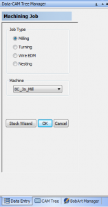 The CAM Tree Manager is where you begin every job. The first step in the new job process is to select the Job Type and the machine that you’ll be using to manufacture your part. As part of the machine wizard, you’re able to program the exact specs from the machine in your shop so that your programming is as accurate as possible. Inputing your machine specs is also useful when you get to the simulation portion of your job set up.
Step 2: Use the CAM Job Wizard to Set Up the CNC Job Type
Once the Data-CAM Tree Manager is open, your Job Type choices are Milling, Turning, Wire EDM or Nesting. Your part type will determine the job type you choose.
Step 3: Use the Stock Wizard to Set Up the Material Type
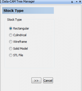 Using the Stock Wizard button from the Data-CAM Tree Manager, you’ll be taken to the Stock Wizard where you’ll set up the stock shape and size. BobCAD-CAM software allows you to select from the following stock types: rectangular, cylindrical, wireframe, solid model, or STL file. These stocks help you determine the minimum size stock you’ll need to machine your part. You also have the option to offset stock in XYZ to encase your part in material or to include extra stock at the bottom to hold your part in place.
The Material Library in BobCAD-CAM comes loaded with over 6,000 materials with built in surface footage and chip load settings. You can assign a default material, create favorites, add/delete/modify materials to custom fit the library to your individual shop’s needs. You can even save and import material libraries to share cutting data between departments, companies, and associates.
Step 4: Set the Part’s Zero Position in the Stock Wizard
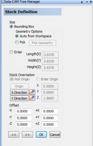
Within the Stock Wizard, you’ll find Stock Definition menu where you can pick the stock orientation and origin. BobCAD-CAM will automatically set up a box around your part with point location in the middle, top, and bottom. You can also select any snap point or point located on your drawing as your part origin.

Step 5: Select CNC Toolpath Machining Operations in the CAM Wizard
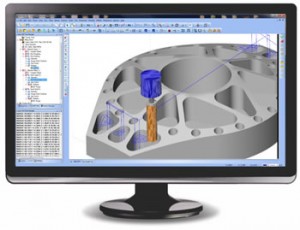
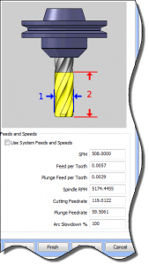 BobCAD-CAM provides Machining Wizards for all toolpath strategies in order to quickly and easily step you through the set up process. Creating a toolpath involves selecting the toolpath type, editing the parameters, and then computing the operation to visually see the results. The Machining Wizards include tooling inputs and access to the customizable tool library, posting parameters, toolpath patterns, leads, toolpath linking and more.
Dynamic Machining Strategies™ allow you to apply any number of applicable toolpath operations to a single CAD feature. This function can save a tremendous amount of time as repetitive geometry selections can be time consuming and redundant. This is also a great way to keeping the CAM Tree neat and organized.
Step 6: Repeat Step 5 as Needed to Rough & Finish the Part
Step 7: Set the Machining Sequence
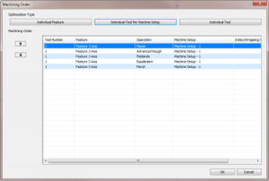 BobCAD-CAM software allows you to choose the machining order for the job. This can be decided by individual tool, machine setup, or individual feature.
Step 8: Simulate the Job
 The simulator provided with BobCAD-CAM allows you to check for machined part deviations, part gouges and machine, tool and tool holder collisions and to calculate your cycle times. These are incredibly useful functions as they can greatly increase your machining efficiency.
Step 9: Post the G-Code Program
BobCAD-CAM provides customizable post processors to fit individual controllers. Once the g-code program is generated it can be sent to the built-in editor with a click of a button. When the g-code reaches the editor you’re able to save the program.
Step 10: Generate the Job Set up Sheets
Generating g-code programming with CAD-CAM software really is that easy. Following these 10 steps will enable to you produce accurate parts quicker, more efficiently and more profitably.
Give these 10 steps a try today! CLICK HERE to download a no obligations trial copy of BobCAD-CAM for free!
Here are some other articles you may be interested in:

Summary
Article Name
CAD-CAM Success in 10 Easy Steps
Description
Following these 10 easy steps can lead to consistent CAD-CAM success that you can depend on to deliver greater productivity and profitability from your machine shop.
Author
Nick Erickson | BobCAD-CAM