One of the primary purposes for using CAM software for CNC part programming is the fact that it provides the necessary element of operator control to the process. Often machinists and programmers need high level control to create efficient toolpath for 3 Axis parts. The solution is to use the BobCAD-CAM 4 & 5 Axis Surface Based Toolpaths for 3 Axis CNC part machining to gain the advantages you need out of a CAD-CAM product.
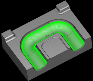 Surface Based Toolpath Linking
The Surface Based machining module includes advanced “Toolpath Linking” controls which are simply methods used to move the tool from one cut path to another efficiently and to best suit the part being machined.
Because there can be so many different scenarios in 3, 4 and 5 Axis machining, BobCAD-CAM’s surface based machining module has included multiple options to choose from for linking one toolpath cut to the next. The advanced options for toolpath linking lets the programmer to determine how and when the tool retracts between cutting steps. These added controls can greatly improve program run time and surface finish quality. Each linking option also includes custom variables that further define the output toolpath results to enable the programmer to further control the toolpath generated regardless of the complexity of the surfaces being machined. Aside from the user being able to choose from multiple options for a machining entry and an exit, the options include 7 different settings that deal directly with gaps along a cut.
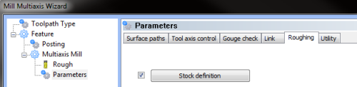
The Follow Stock linking option uses the stock geometry shape to perform linking motions. This is only available when the Stock Definition check box is selected, located in the Roughing tab of the BobCAD-CAM Machining Wizard as you can see in this image below. All machining options in BobCAD-CAM software are accessible through wizards that step the operator through creating toolpath.
The user can also adjust the Small Gap Size. This sets the threshold size for small gaps in one of two ways.
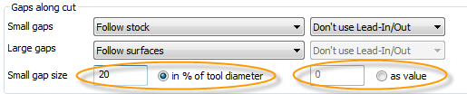
The In % of Tool Diameter feature is a percentage of the tool diameter. The As Value feature determines the actual size of small gaps.
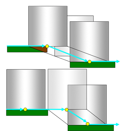
The following image shows small gaps (3) with Direct selected, and large gaps (4) with Retract to Feed Distance (2) chosen as one of the parameters of linking.
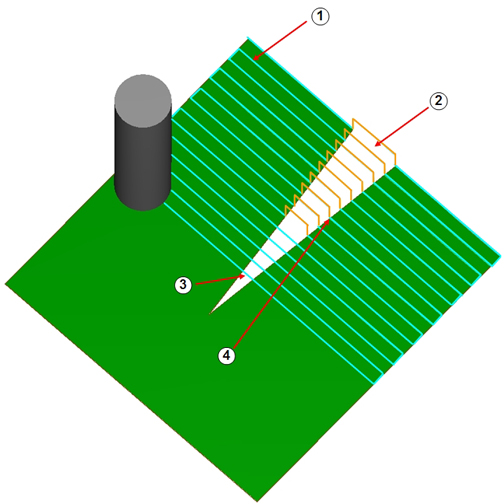
Direct Link Style: This tells the tool to treat the gap as if it doesn’t exist and links the toolpath segments directly with no tool retract.

Retract To Feed: This causes the tool to retract to the Feed distance value before connecting to the next toolpath segment.
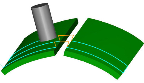
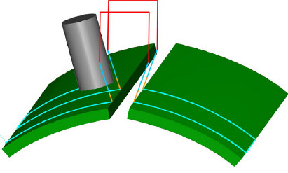
For those types of parts that have complex contours there is the option to Follow Surfaces as you can see in this next image.
The “follow surfaces” option is where the toolpath attempts to follow the geometry surface and create the toolpath as if the geometry is closed.
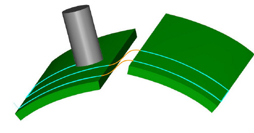
The Blended Spline linking option creates a spline that is blended between the two surfaces to link the toolpath segments. This linking option is good for 3 Axis high speed style toolpaths where complex surfaces exist at various levels across the part.
The Step linking option can also be used. This is where the software creates a step to link toolpath segments when needed across the part.
The Retract To Clearance linking option causes the tool to retract to the Clearance area before connecting to the next toolpath segment.
In addition to the Gaps Along Cut toolpath linking options there is the “Links Between Slice” linking feature sets and the “Links Between Passes” linking feature sets.
Altogether there are over 20 toolpath linking options in addition to the special features that are associated with tool lead-ins and lead-outs, therefore providing the operator a superior level of toolpath control for machining 3, 4 or 5 Axis parts. The images and much of the information in this article are dirived from the BobCAD-CAM “Help” system which is designed to ramp the operator up quickly on the advanced features of the software.
To learn more about what Surface Based Toolpaths can do for your CNC productivity, you can call BobCAD-CAM direct at 877-262-2231.
Download a Free Demo today! Click HERE
Here are other related articles that you may be interested in:


Summary
Article Name
CAD-CAM Surface Based Toolpath Linking & Leads for 3 to 5 Axis CNC Machining
Description
BobCAD-CAM CNC Programming software provides a surfaced based module that provides advanced toolpath linking options to give machinists more control for their 3, 4 & 5 Axis programs.
Author
BobCAD-CAM, Inc.