Whether you are looking for performance or individuality, creating a custom-built valve cover is actually a lot easier than you think. Using CAD-CAM software like BobCAD-CAM V30, let’s go through the steps of making a one-of-a-kind valve cover for production or personal use.
Wireframe
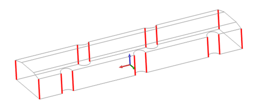
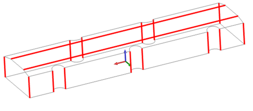
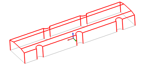
Let’s kick this off with some wireframe sketches, looking at our model from the top and the side.
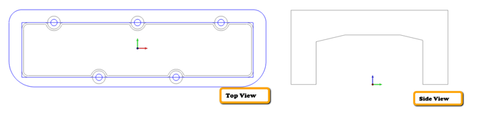
Tip: As you start to create your wireframe layout, try to avoid over filleting. Fillets can be added at later stages in the design process to your model.
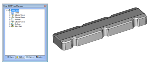
CAD History Tree
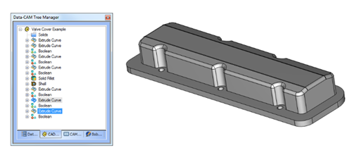
This example uses a combination of surface design and editing tools.
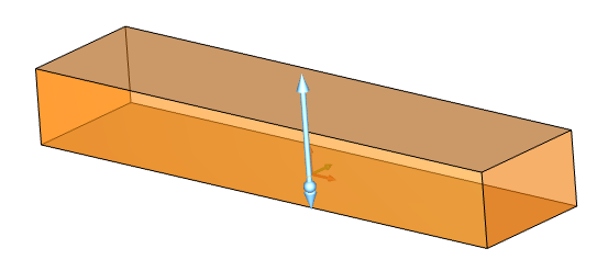
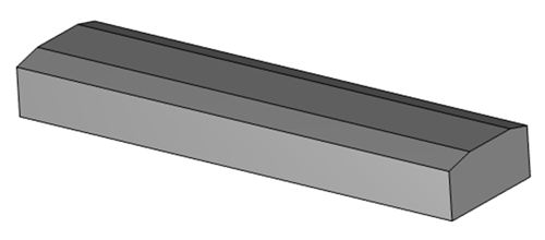
Let’s start with extrude curves, where I select the top profile of your valve cover, we are extruding in Z.
Your next step is to extrude the side profile in X, as to extend past the edges of the top profile model.
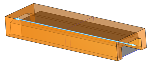
With these two solid bodies, the next step is going to boolean subtract the side profile model from the top profile model.
Tip: When utilizing boolean subtract, the first model you select is the one you’ll want to keep. Use your second model as the one you want to cut from the first model.
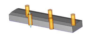
Valve Cover Retainer
Next, add clearance for the retaining bolts. We’ll use the same process of extruding that is followed by boolean subtract.
Subscribe to BobCAD-CAM's CNC Software Blog
Join your fellow manufacturers! Get BobCAD-CAM’s latest CAD-CAM articles straight to your inbox. Enter your email below:
Fillets
We now have the basic layout of our custom valve cover, so the next step is going to be adding some fillets to break the edges. Fillets can be as fun as papercuts sometimes, but once you get the hang of it, it’s like second nature.
There are a few basic rules that you should follow to get quality results, one of which is to define multiple radiuses in a single selection. The next is to use “tangential edges” for best results.
½ fillet is going to be the first selection for the valve cover. Launch the solid fillet feature, select tangent propagation, input .5 as your radius valve and start picking edges.
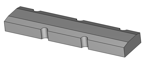
Tip: To assist with edge selections, hit “S” on your keyboard. This toggles the shading of surfaces on and off. The image above shows shading that is turned off.
The next step is going to be altering the radius valve to .25 and continue selecting. For our example, we need to select shape edges of the retainer clearance surfaces.
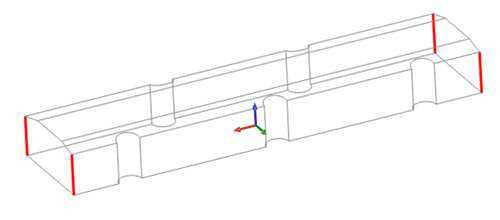
As a recap: In order to get the best results with fillets, we must work with the smoother edges, or tangential edges. This is why we begin with the vertical edges in our selection process. These edges will get rounded over and yield a good geometry condition for the next fillet that we want to put around the outside edge of the valve cover.
It still may not be 100% clear, but we still have a few sharp edges that need smoothing out. Running the length of the valve cover, we must angle surfaces and need to break that edge before we can go to the outside profile.
With our addition of the outside edges, we can now hit “OK” on the fillet command and look in awe at our marvelous results! It’s worth noting that all of these fillets were created with a single fillet feature located in our CAD history tree.
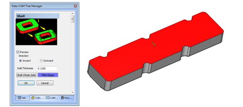
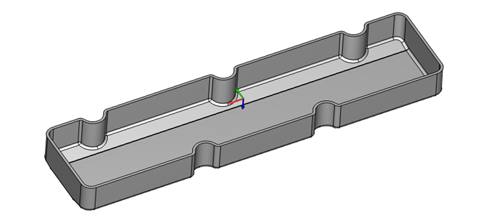
Shelling
Do you love your valve cover yet? Ok, let’s keep going Machine Heads. Your next move is going to be shelling the part, creating the inside cavity of your valve cover.
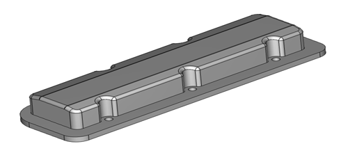
The last step in this build is going to be adding the flange on the bottom. Again, we’ll use extrude curves and boolean process to add the flange. Your end result should look like this.
CAM
Let’s take a look at what steps we would use to set up and machine this part. Based on our model, we will have 2 setups. One for the top and one for the bottom of the valve cover.
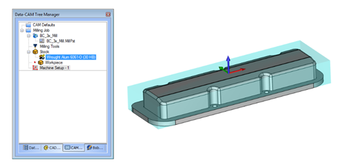
Machining Job / Job Type
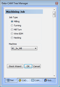
As we get started in CAM, we need to select a job type, machine and setup stock. These steps instruct the CAM software which kind of Toolpaths you’ll have access to, what your machine is going to be capable of and where your zero and stock are located.
Using our BobCAD-CAM stock wizard, we’ll set up a rectangular stock for the limits of our model and set the work offset to the top center.
Toolpath
As we observe the valve cover, we must decide which Toolpaths we want to use and what sequence we want to use them in so we can effectively and efficiently machine our part. Depending on the job, faster cycle times may take priority over surface finish or the other way around. Now, don’t get me wrong, quality surface finishes should always be a priority if you wish to maintain repeat customers.
Roughing
A good starting point is to quickly remove stock material from the outside of your model.
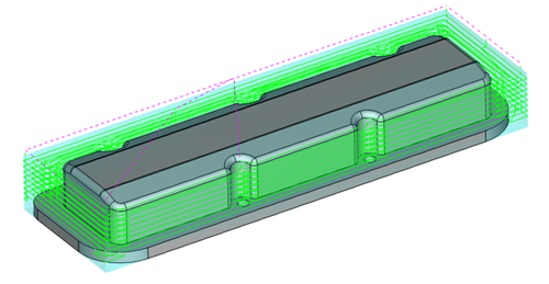
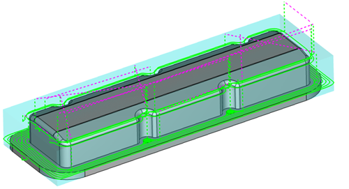
Using Z Level Rough, like in the image above, works just like a 2D pocket. Only, instead of being contained by a boundary in 2D, this Toolpath follows the contours of the model. For more of a modern approach to your machining, you may decide to use an adaptive Toolpath. This would offer greater efficiency and a shorter cycle time, like the example below.
Both Toolpaths will rough your part, it just gives you 2 different approaches when it comes to depth of cut (DOC) and width of cut (WOC)/ Stepover.
Z Level Rough takes a shallow DOC with a more aggressive WOC, taking many steps to get down to the bottom.
Adaptive Toolpaths take a very aggressive DOC with a shallow WOC. With this method, we side rough at 2X diameter using special Toolpath motion to ensure smooth and consistent cutting. Another great advantage of the modern adaptive approach is using intermediate steps.
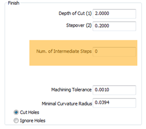
Adding intermediate steps knocks down additional stock that can be left over based on your DOC.
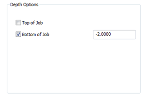
Depth options
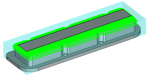
Sometimes you may want to limit how deep your tool cuts down, like we do in this example. We don’t want our tool to cut past the top of the bottom flange. There is a simple solution to this and it’s called depth options. It lets the user define an absolute value from the machine setup location for the top and bottom on cutting.
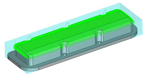
Advanced Planar
At the top of our model we have a couple fillets and 2 angled surfaces. Using a 3D Toolpath called planar, the tool moves back and forth at a defined angle along whatever surfaces you’ve selected. Planar is optimal for shallow surfaces. As surfaces steepen, a larger scallop is made.
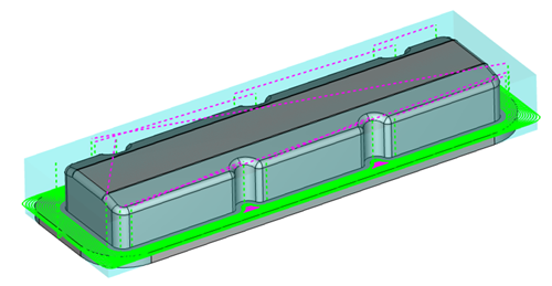
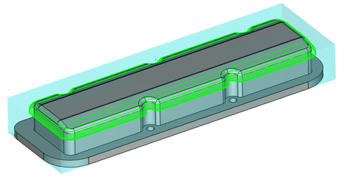
Advanced Z Level Finish
This Toolpath acts more like a profile feature, where the tool will walk around the outside of your part, making it better for steeper surfaces. A larger scallop is made where surfaces begin to shallow out.
Using both planar and Z level finish will allow you to effectively program steep and shallow areas of your parts. You will also be pleased to know that adaptive Stepover options are available for advanced planar and advanced Z level finish. This gives you greater control over shallow or steep areas of your part with the corresponding Toolpath.
With this example, instead of using both planar and Z level finish, I selected advanced Z level finish with adaptive step down to machine the angled surfaces and fillets. Choosing a spiral pattern allows you to keep your tool in the cut the whole time and remove the link moves for each step-down.
1st Side Finish
So far we have programmed the first setup of the valve cover. We used adaptive Toolpath to rough out our material, then an adaptive Toolpath to finish it. There are some other things we could have done to make this valve cover really special, like engraving. However, the main goal was to have a basic understanding of some of the machining options available to you to make your own, custom valve cover.
To give BobCAD-CAM’s latest software a try click HERE. Better cuts, fewer steps, more profits.
You’re one click away from subscribing to BobCAD’s YouTube channel. Click the link below for tips, how-tos and much more!
Summary
Article Name
Design and Machine Custom Valve Covers Using CAD-CAM
Description
Whether you are looking for performance or individuality, creating a custom-built valve cover is actually a lot easier than you think. Using CAD-CAM software like V30, let’s go through the steps of making a one-of-a-kind valve cover for production or personal use.
Author
Michael A. Downss
BobCAD-CAM Software