Tech Tuesday is a weekly blog that addresses some of the most common questions and concerns that I hear throughout the previous week from users of BobCAD-CAM software. Both customers and future customers are more than welcome to leave a comment on what they would like to see covered for the following Tech Tuesday.
Today’s Tech Tuesday is aimed at teaching the design workflow for 3D modeling (Part & CAD Tree). If you ever wanted to design a part with text or a logo cut into a curved surface then this is the right place for you to be!
Getting Started
When it comes to creating 3D design, BobCAD’s CAM software is loaded with many surface and solid model features. Which one to use and in what order can be daunting at times. That’s why this Tech Tuesday covers all the steps you need to follow to make a solid with text or a logo cut into a curved surface.
Step 1. Creating Wireframe
There are lots of ways to get started with a 3D design. Sometimes you start with solids, but in today’s example, we’ll start with wireframe. We need 2 sets of wireframe geometry for this project.
A. The text or logo you want to cut into the curved surface.
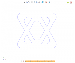
In our example, we used the shape library and created a triangle. We offset the profile and used fillets to round off all the edges. Then we rotated it 180 degrees and made a copy. Our next step is to combine these two shapes using 2D boolean.
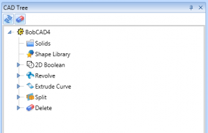
At this point, your CAD Tree will look like this.
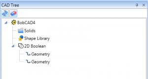
We’ve completed our first set of geometry and now we are on to the next set.
B. The cross section of your revolved surface.
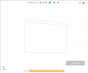
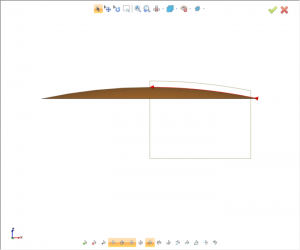
Our next step is to create the revolved profile for our model and the offset curve for our splitting surface. To create the revolved profile, we changed our UCS (User Coordinate System) to a front view. We created a rectangle, then a 3 point arc and trimmed the profile so we only have half the shape. Next, we used offset to create an offset profile. The offset profile is used for our split surface. The deeper we want the text or logo, the greater the offset profile value. At this point, nothing has changed in our CAM Tree but we have created all the wireframe geometry we need for this project.
Step 2. Going from 2D to 3D
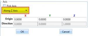
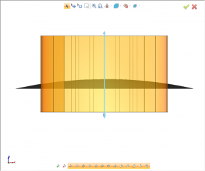
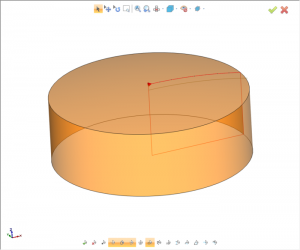
Now that we have all the wireframe geometry we need, our next step is to start creating surfaces and solids. In our example, we’ll create the split surface first. To do this, we’ll use a revolved surface.
When using a revolved surface, make sure to change the axis setting to be along the Z axis.
Now that we have our revolved split surface, our next step is to extrude our text/logo.
We want to make sure that when we create our extruded text/logo that it goes past the point of intersection with the split surface.
Subscribe to BobCAD-CAM's Tech Tuesday Blog
Join your fellow machinists. Get the latest Tech Tuesday CAD-CAM articles sent to your inbox. Enter your email below:
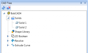
At this point, your CAD Tree will look like this.
Our next step is to split the extruded text/logo with our split surface.
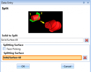
We will select the extruded text as our solid to split and the splitting surface is the revolved surface we previously created.
Splitting is used to “break” the solid into 2 pieces; this way we can remove the part of the solid we don’t want and keep the part we do want. Using split “cuts”, our extruded text with our curved surface at the depth we want the text/logo to go into the part.
After deleting the part of the solid we don’t want, our extruded text/logo looks like this.
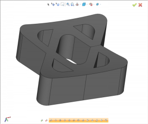
As you can see, the bottom of the text/logo is now curved to the shape of our split surface.
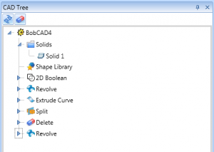
Here is what our CAD Tree looks like.
Next thing we want to do is to revolve the solid body of our part. We will use the revolved cross-section wireframe to create this body.
Here is what our CAD Tree looks like at this point.
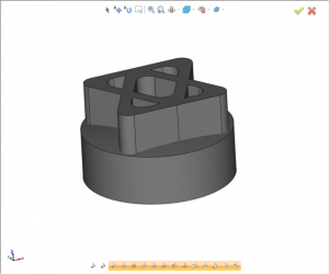
We are now in the final steps of our design. We have our extruded text/log and our solid body, our last step is to boolean the 2 solids to get our desired result.
Before Solid Subtract boolean.
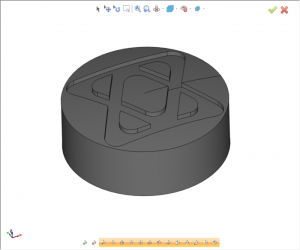
 After Solid Subtract boolean.
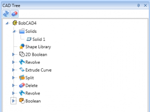
Here is what our CAD Tree will look like.
That’s it, we’re done! We have the result we were after. Keep in mind this workflow can be used in many different applications and we recommend you give it a try. Thanks for reading another Tech Tuesday; see you next week!
Use this link to download the sample file for this project!
If you want to watch a step by step video of this workflow, use this link. This video is in our BobCAD After Dark Facebook group (if you aren’t a member, I highly recommend you become one).
You’re one click away from subscribing to BobCAD’s YouTube channel. Click the link below for tips, how-tos and much more!