Questions? Call Us to speak with a CAD CAM Pro!
4th Axis in BobCAD-CAM and BobCAM for SOLIDWORKS is one aspect of programming that evolved the most in recent releases. So in today’s blog, we’ll focus on the most important new features and their impact on programming and cutting times. In addition, we will look at how these new strategies compare to previous; so that users of previous versions can better understand the evolution of 4th axis programming with BobCAD CAM and the benefits of these new strategies.
Automatic Recognition of Drills
Although BobCAD-CAM recognizes radii as possible holes and automatically defines their starting position, angle and depth since version 29 and BobCAM V5, geometry selection found in earlier versions did not recognize the “Type of hole being programmed”.
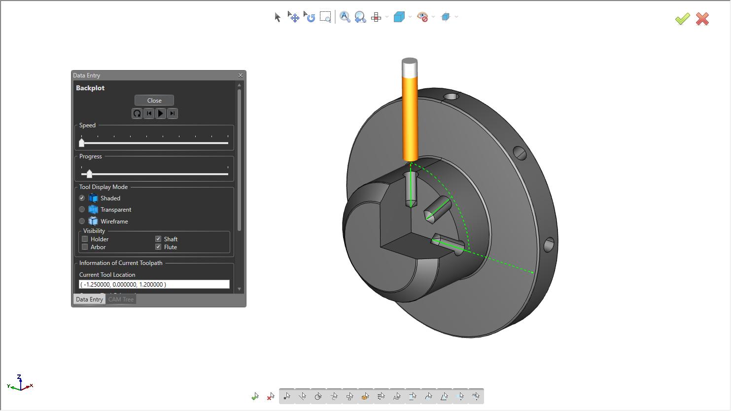
BobCAD-CAM 4 Axis Cross Drilling Example
Imported Geometry?
For example, holes that have multiple features like a chamfer or flared (pocket / counterbore ). In previous versions, sometimes selecting solid models with radii and fillets were confused as possible holes, they also did not have a database of holes like the one we have now.
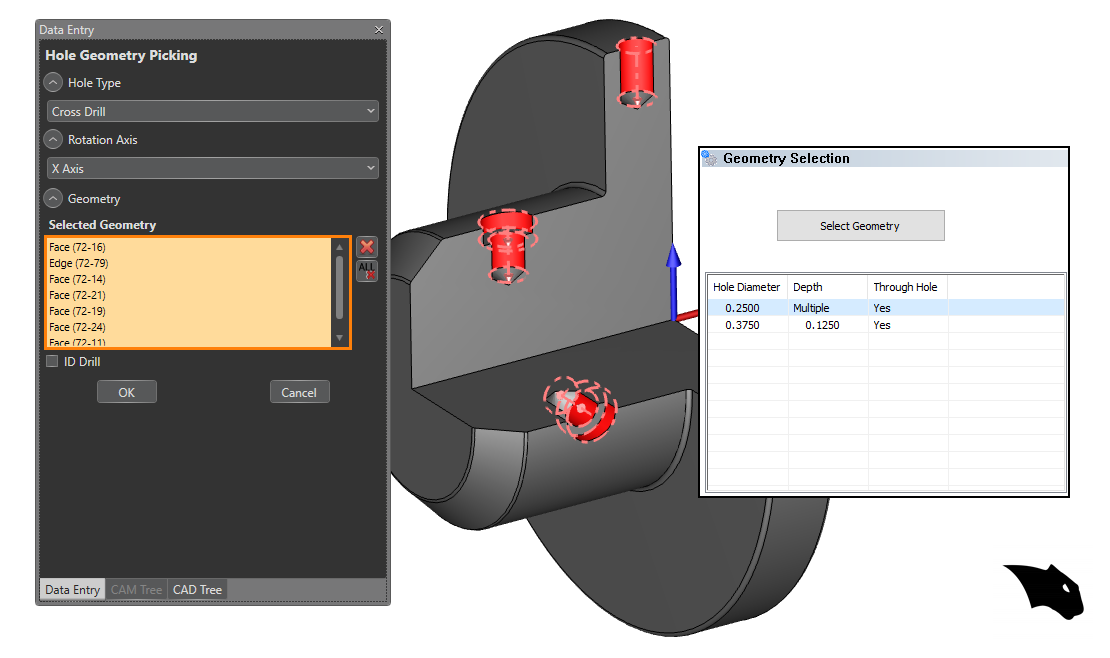
Hole Recognition – Reads Hole Types
Hole Recognition makes hole programming easier, Using the hole size filer and your solid model, BobCAD-CAM automatically list all the holes sizes and types of holes found. Simplifying selection while putting the power of choice in your hands. Gone are the days of sorting holes sizes by color, layer or selection manager. Hole Recognition finds the holes, you decide what to do with them.
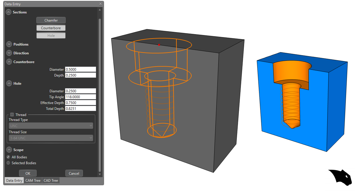
Design With BobCAD?
New automation found in Advanced Holes not only speeds up the hole design process, it also speeds up CAM. Creating Holes in 3D with properties that our CAM software reads to process size depth and thread data.
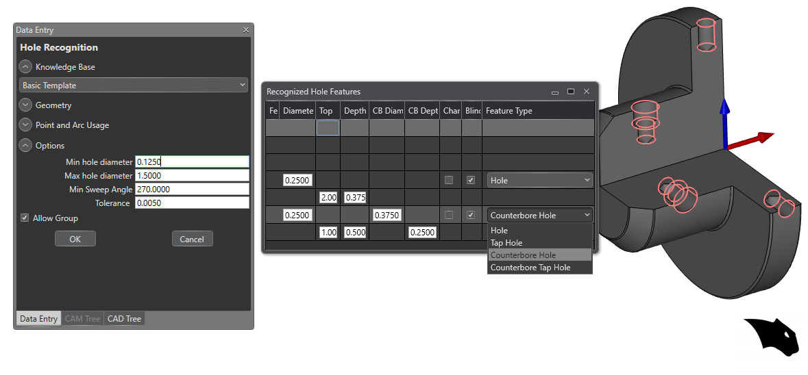
Cutting Data For Processing Holes (knowledge base)
Cutting Data For Processing Holes ( Knowledge base) User can now pre-program the hole taking into account factors of its geometry, such as the following examples: If the hole is greater than .75 it must have 3 drilling operations, if the hole is deeper than .5 it must have pecking, if the hole has a thread it must have a chamfer.
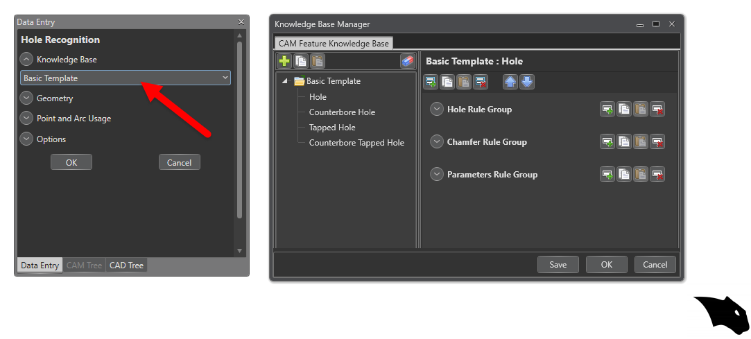
Being able to preset these parameters and have the software automatically recognize the properties of the hole is a huge time saver in any programming process. Find tune your automation with a user editable knowledge base and hole recognition.
Advanced Holes for design, Index systems, and Hole Recognition helping you design and program holes in less time.
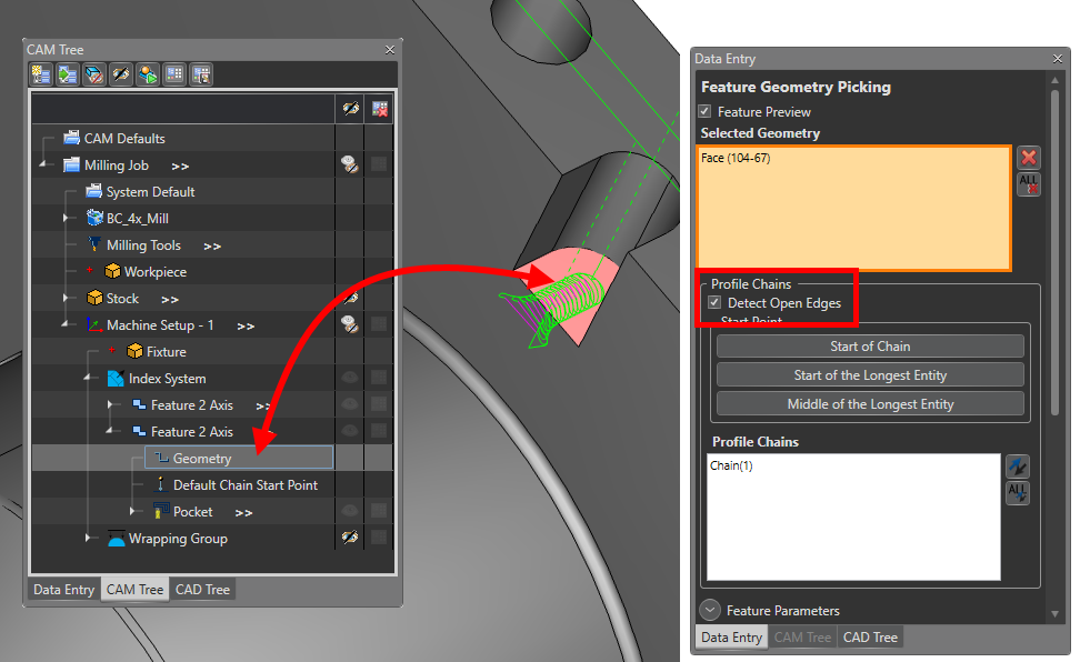
Recognition of Surfaces and Solids for 2D Operations in Multiaxis
Easier geometry selection is the aim of what seems like a minor detail. The fact that the programmer no longer needs to carry out geometry development processes (unwrap geometry) to program cylindrical parts, ( converting to wire frame ) or extracting the edges of the profiles and pockets,( making dotted lines ) or needing to modify the type of line to specify open areas is A HUGE TIME SAVINGS.
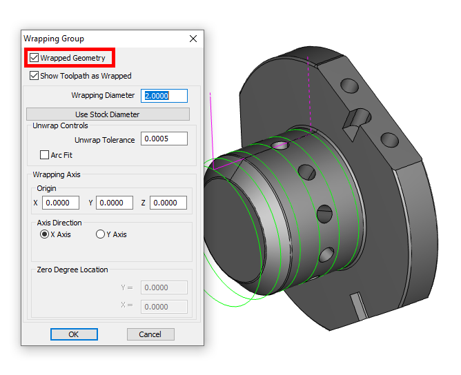
Now users can take a solid developed in BobCAD-CAM or any other CAD, and simply carry out the 4-axis programming process directly from the solid, eliminating the hours of geometry preparation common in previous versions.
Improvements to 4th Axis Rotary
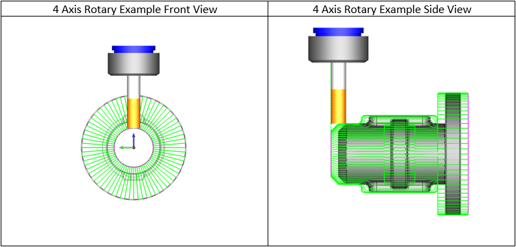
Roughing with your 4th Axis? If you’ve used 4 Axis Rotary in the past, You’ll notice that the toolpath did not adapt to the stock material of the part, forcing the user to perform hundreds of unnecessary steps in the air like the one in the image below.
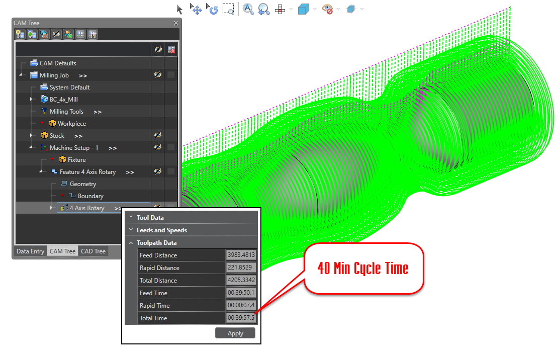
Improvements to how the system recognizes material, whether cylindrical or pre-designed has big impacts on your roughing cycles. The recent improvements to stock consideration found in 4 Axis Rotary will improve your cycle time by eliminating all movements outside of the material.
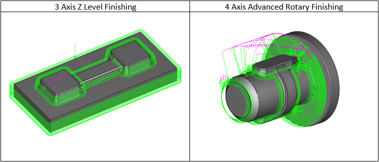
50% Decrease in Cycle Time
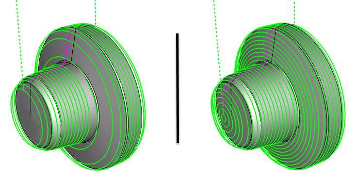
At the same time, finishing with 4 Axis Rotary now adapts to changes in the surface by modifying the distance between cuts to achieve perfect finishes in any type of surface as you can see in the images below:
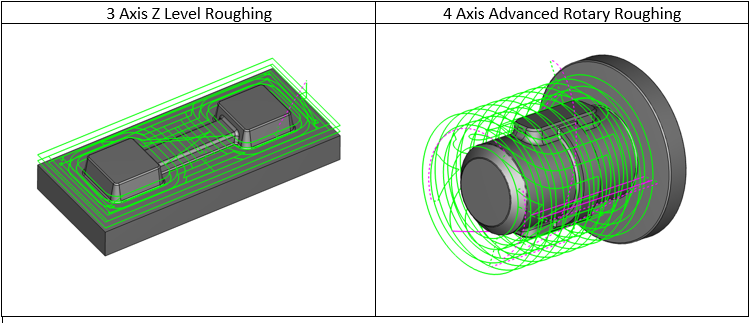
4th Axis Advanced Rotary Roughing & Finishing
Take your 4 Axis to a whole new level with 4 Axis professional. Rotary users gain access to new options that just make 4 Axis work easier. Let me explain, when it comes to 3D milling the 2 most popular cutting strategies are planar and Z level.
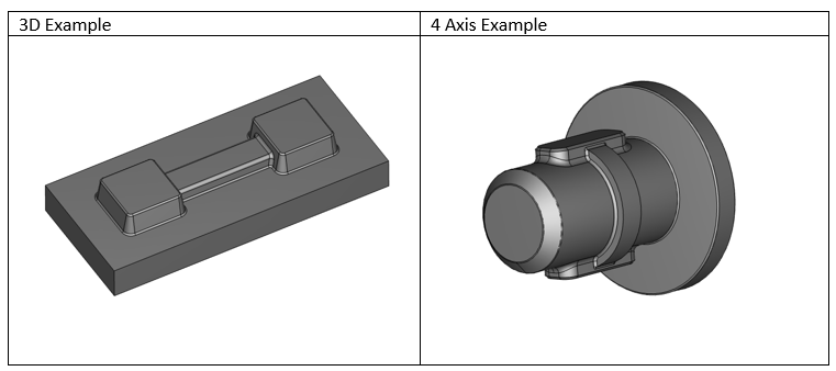
Planar is that back and forth cutting, just like rotary. Where Z level steps down in Z and then cuts around. With prior versions there was no “ Z Level” equivalent for Rotary 4 Axis programming, that was until Advanced Rotary.
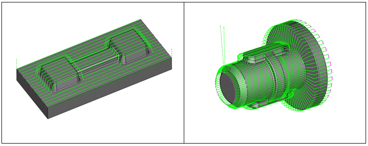
This new toolpath operation brings the power of Z level toolpaths to Rotary and they just make 4 axis programming easier!
These two new strategies improve the programming processes of complex parts such as helical, bi-helical gears, and screws of all kinds since they automatically find the roughing and finishing areas just by selecting the complete solid.
As we know, in previous versions the only strategies that we could use for this type of part were the surface based toolpaths found in the multi axis menu. Although these strategies are very effective and support simultaneous motion, they are complex to define, due to the review of normals of the surface, lateral limitations, tool tilt definition. This procedure must be carried out for each surface separately, considerably increasing the programming time.
Advanced Rotary speeds up programming with it’s “select the whole model and go workflow”
Struggles of 4 Axis Roughing
Roughing large amounts of material with your 4th Axis is problematic for workflow and cycle time. Traditional Rotary toolpaths point to the Axis of rotation, thus cutting with the center of the tool. Tools suffer when they remove large amounts of material; center cutting vs side cutting accelerates tool wear or breakage. Slowing down cycle times, while increasing your cost per part👎
For this reason, users will first turn down part profiles on the lathe. Or, if they want to keep the part on a single machine, they will use 3 Axis operations with 4 Axis indexing to remove material.
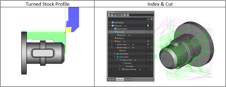
Both of these methods suffer in efficiency, either due to multiple machine part handling, or the programming process and results. To truly impact 4 Axis roughing in cycle time, tooling costs and programming efficiency, and new style of toolpath was needed.
Solution: Turn Milling
4 Axis CAD CAM reaches a new milestone with Turn Milling, truly helping 4 axis programmers process parts more efficiently, while reducing cycle time and tooling costs.
Turn Milling always removes material with the side of the tool, so they last longer! It’s a single machining feature which makes it easy to use and only requires one setup making it efficient for the shop floor.
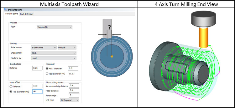
This 4 Axis toolpath emulates the turning process of a lathe on your 4th to gain its efficiency. The turning aspect of Turn Milling is so vital when removing large amounts of material.

All these changes have been applied to the 4th axis system only in the last 3 Versions and each of them represents a great saving of hours of programming and machining time, for this reason we recommend watching all the training videos, attending the webinars/training events , read our blogs and use for your online training. BobCAD is constantly evolving, you may be wasting time and money just due to your lack of knowledge.
Thank you all very much and we look forward to seeing you at the next webinar on this topic:
The Evolution of the 4th axis:
Related Video
Download a demo of New BobCAD and try these features today!
What’s the best way to keep up with BobCAD’s new features and how to use them? It’s our weekly training events, keeping you up to speed on everything BobCAD CAM, Click Here to sign up, it’s Free.
Questions? Call Us to speak with a CAD CAM Pro!