Tech Tuesday is a weekly blog that addresses some of the most common questions and concerns that I hear throughout the previous week from users of BobCAD-CAM software. Both customers and future customers are more than welcome to leave a comment on what they would like to see covered for the following Tech Tuesday. Enjoy!
The Problem
One of our customers came to us on our AfterDark Facebook group recently looking for some help in an older version of his BobCAD software. He says, “I do a ton of 3D machining, this simple little thing came up and I’m stumped. I want a 1/8″ ball mill to follow this toolpath with an offset of 1/2 the tool but at the radius and bottom of the path, the tooltip follows the path. The 3D wireframe only follows the tooltip.”
This led Director of Partner Products & Technical Services, Alex Cole, to create this Technical Tip for him and others that may be having the same issue. “With my tutorial, you do not actually need to run the tool at the center. I show you how to create the geometry that will compensate for the tip correctly,” says Alex. Now, let’s see how this is accomplished.
The Solution
To cut to the center of the ball tool without actually setting your toolpath or the machine up to the center of the tool can be accomplished on this example geometry and by following the steps below.
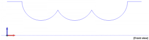
Example Geometry:
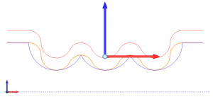
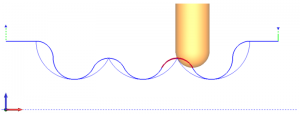
1. Using the offset command, we want to offset the geometry in an upward direction by the radius of the tool you wish to use. This is shown in the image below.

You want to make sure the ‘Use Sharp Corners’ option is turned off in the Offset Contour command.
Subscribe to BobCAD-CAM's Tech Tuesday Blog
Join your fellow machinists. Get the latest Tech Tuesday CAD-CAM articles sent to your inbox. Enter your email below:
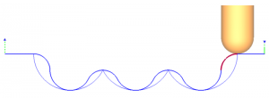
2. You will now use the Translate command to move the geometry we created with the offset, back down by the radius of the tool. This will then put the geometry where we need so we can create the toolpath. Use the image below for reference.
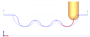
 3.
3. With this new geometry drawn out how we want it converted in G-code, we created a
3 Axis Wireframe toolpath to follow, allowing us to achieve the desired cut. Just follow these steps and you will be cutting like a pro!
 That’s about all the time we have for today. Thank you for reading another Tech Tuesday; see you next week!
Start your Test Drive.
Have questions? Call us at 877-838-1275.
You’re one click away from subscribing to BobCAD’s YouTube channel. Click the link below for tips, how-tos and much more!
To see if BobCAD’s Mill Turn software is right for your shop,
Summary
Article Name
Tech Tuesday: 3D Wireframe CAM Software Toolpath Tricks
Description
With my tutorial, you do not actually need to run the tool at the center. I show you how to create the geometry that will compensate for the tip correctly.
Author
Alex Cole
BobCAD-CAM Software