Many people have heard of or seen what is called “Adaptive Machining” also called “High Speed Machining”. Some have been able to figure out what makes up this methodology and have successfully applied it, but many have not. Success in investigating and applying Adaptive Machining is dependent on understanding exactly how this machining method works and most importantly, why it works. This document has been created with the aim to assist those who are not familiar with Adaptive Machining and do not know where to get started with implementing this method into their manufacturing processes.
The goal is to achieve faster material removal rates and extended tool life through optimization of the machining process using new or existing equipment. To achieve these gains, one must understand each part of the process and how they work together to achieve this goal.
Tooling
When working with Adaptive Machining techniques, it is important to understand the impact of tool selection and tool balance. Tool selection is still mainly driven by the requirements of the part, determining things like Diameter, Corner Radius, etc… The important detail to understand is that the tool must have the proper relief angle allowing for higher feedrates. Too much relief angle results in a weak cutting edge that will quickly break down and fail. Too little relief angle results in rubbing at high feedrates. This rubbing causes rapid heat buildup and tool failure. A balance must be found based on the tool and workpiece material being used.
One way to increase the possible feedrate is to use a tool with more cutting flutes. These tools work well on machines that do not have high maximum spindle speeds, but, care must be taken to make sure the chips can be successfully evacuated from the cutting flutes. Without improper chip evacuation, the tool will quickly load up and fail, ruining the tool and possibly the workpiece.
Helix Angle
When selecting tools, you want to use tools that are specifically designed to dampen vibration and have a helix angle designed to reduce spindle load and the quick evacuation of chips.
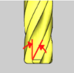
Traditional tooling uses lower helix angles from 15 to 30 Degrees. Newer tooling intended for higher feed applications where chip evacuation is important will use helix angles from 30 to 60 degrees.
Balance is very important as the spindle speed increases. Vibration in the tool can have great impacts on surface finish and rapid tool wear. It is understood that for every .00039in(0.01mm) of runout for a tool, it can decrease tool life by up to 50%. When runout is encountered, a single flute of the tool will be cutting more than the others. This causes rapid wear on the flute. Because of the accelerated wear, heat will begin to build up in the tool and workpiece resulting in a rapid breakdown of the cutting edges on the tool and possible work hardening of the part.
Workpiece Setup
When a tool is in the material and cutting, different radial and axial forces are being exerted on the workpiece and the tool. These forces must be managed to allow for the best possible results of the machining operation. The forces being exerted on the workpiece result in vibration and deflection of the workpiece. The result is the reduction of the finish that can be achieved. Rigid setups with maximum support are required to ensure the best possible results from the machining operation.
What is Radial and Axial Chip Thinning
Radial and Axial chip thinning is the reduction in thickness of the actual chip being generated based on the tool engagement into the workpiece. Because of this chip thinning, you must run a tool at much higher feedrates to maintain the manufacturers recommended chip load, thus reducing wear, increasing tool life and surface finish.
Axial Chip Thinning is experienced when a radius (Ball) endmill is being used and the stepdown or vertical engagement into the material is less than the radius of the cutter.
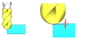
When Axial Chip Thinning is experienced, the effective diameter of the tool is also changing. In the right image above, you can see the effective diameter of the tool is much smaller than the actual diameter due to material engagement. This will affect the surface finish due to changes in the actual SFM vs. the programmed SFM for the tool.
Radial Chip Thinning is when cutting with the side of the tool. You will experience chip thinning when the stepover value is less than the radius of the cutter.

Speed and feed data provided for cutting tools in today’s market is provided by giving the user SFM(Surface Feet per Minute) and FPT(Feed Per Tooth) values. Using these two values the user determines the spindle speed and feedrate at which to run the cutting tool.
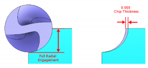
The previous images show a radial stepover and the FPT. You can see that a feedrate of 0.005 IPF the tool is indeed removing the desired chip thickness. But notice what happens to the thickness of the chip as you decrease the stepover amount.
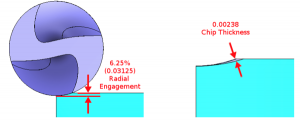
This image shows the chip size when the stepover has been reduced to 6.25% or 0.03125 inches. Notice now the thickness of the chip has been reduced to 0.00238.
NOTE: For the purposes of this writing, the effects of deformation of the chip material during the cutting action has been excluded.
Because the thickness of the chip has been decreased, the tool is no longer cutting at the recommended value. Because of the thinning of the chip, you are now able to increase the feedrate to return the chip load to the desired value. To successfully increase the feedrate to account for Chip Thinning, there is an important factor that cannot be ignored and that is the tool’s engagement into the material.
Subscribe to BobCAD-CAM's CNC Software Blog
Join your fellow manufacturers! Get BobCAD-CAM’s latest CAD-CAM articles straight to your inbox. Enter your email below:
How to Calculate
To figure out how to adjust the feedrate of the path to account for Radial Chip thinning, you must first find the Radial Chip Thinning factor. With this factor, you can then find either the Unit Per Minute feedrate value or the Feed-Per-Tooth value that should be used to achieve the actual desired chip thickness.
The formula for Radial Chip Thinning Factor is the following:
Click HERE for the formula
Sequence of calculation to get Radial Chip Thinning Factor:
1. Result = WOC * 2
2. Result = Result / Effective Diameter
3. Result = 1 – Result
4. Result = Result Squared
5. Result = 1 – Result
6. Result = Square Root of the Result
Now the Result contains the chip thinning factor. With this, you can calculate the current chip thickness and you can also use this factor to calculate the new feedrate that should be used to obtain the desired chip thickness.
Actual Chip Thickness
To see the actual chip thickness the calculation is the following: Click HERE for the calculation
The formula for Axial Chip Thinning Factor is the following:
Click HERE for the formula
Sequence of calculation to get Axial Chip Thinning Factor:
1. Result = DOC * 2
2. Result = Result / Effective Diameter
3. Result = 1 – Result
4. Result = Result Squared
5. Result = 1 – Result
6. Result = Square Root of the Result
Now the Result contains the chip thinning factor. With this, you can calculate the current chip thickness and you can also use this factor to calculate the new feedrate that should be used to obtain the desired chip thickness.
Actual Chip Thickness
To see the actual chip thickness the calculation is the following: Click HERE for the calculation
Feedrate Adjustment
To find the new Feed Adjustment Factor use the following:
Feed Adjustment Factor = Axial Chip Thinning Factor * Radial Chip Thinning Factor
NOTE: For applications where you are only applying Radial or Axial Chip Thinning and not both, simply use the appropriate Axial/Radial Chip Thinning Factor in place of the Feed Adjustment Factor.
To find the FPM value, use the following:
New FPM = Starting FPM / Feed Adjustment Factor
To find the new FPT value that will result in the correct chip thickness use the following:
New FPT = Original Feed Per Tooth / Feed Adjustment Factor
Example Calculations:
Example 1 – Radial Example
| Cutter Diameter (CD) |
0.500 |
| RPM |
1500 |
| Feedrate |
30.000 |
| Number of Flutes |
4 |
| Feed Per Tooth |
0.005 |
| Width of Cut (WOC) |
0.032 |
Using the data from the table above, we find the following using the formulas described.
| Chip Thinning Factor |
0.489505873 |
| Actual Chip Thickness |
0.0024475 |
| New Feedrate |
61.2862 |
| New Feed Per Tooth |
0.01021 |
Example 2 – Radial Example
| Cutter Diameter (CD) |
0.500 |
| RPM |
1500 |
| Feedrate |
30.000 |
| Number of Flutes |
4 |
| Feed Per Tooth |
0.005 |
| Width of Cut (WOC) |
0.178 |
Using the data from the table above, we find the following using the formulas described.
| Chip Thinning Factor |
0.957630409 |
| Actual Chip Thickness |
0.004788152 |
| New Feedrate |
31.3273 |
| New Feed Per Tooth |
0.00522 |
Example 3 – Radial and Axial Example
| Cutter Diameter (CD) |
0.500 |
| Cutter End Radius |
0.250 |
| RPM |
1500 |
| Feedrate |
15.000 |
| Number of Flutes |
4 |
| Feed Per Tooth |
0.005 |
| Width of Cut (WOC) |
0.031 |
| Depth of Cut (DOC) |
0.031 |
Using the data from the table above, we find the following using the formulas described.
| Radial Chip Thinning Factor |
0.482311103 |
| Axial Chip Thinning Factor |
0.669397386 |
| Actual Radial Chip Thickness |
0.00241 |
| Actual Axial Chip Thickness |
0.00335 |
| New Feedrate |
46.460 |
| New Feed Per Tooth |
0.01549 |
Toolpath Strategy
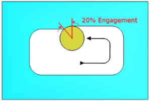
Traditional machining techniques involve cutting at slower feedrates with varying tool engagement. Take a pocket for example. When cutting a pocket with standard techniques, the engagement of the tool will fluctuate as the tool encounters direction changes such as in a corner.
As seen in this image, the engagement while cutting along the wall of this pocket is 20%. Because of this engagement, Radial Chip Thinning is experienced. The feedrate could be increased to achieve a reduction in cycle time, but as the tool continues to cut into the corner you can see the engagement of the tool is greatly increased.
As seen in this image, the engagement while cutting along the wall of this pocket is 20%. Because of this engagement, Radial Chip Thinning is experienced. The feedrate could be increased to achieve a reduction in cycle time, but as the tool continues to cut into the corner you can see the engagement of the tool is greatly increased.
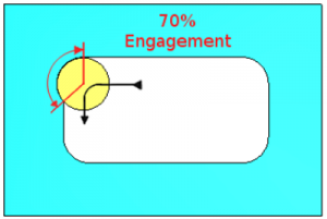
As the engagement of the tool into the workpiece increases, the pressure exerted on the tool also increases. This often leads to chatter that causes a poor surface finish. Another side effect of the increased tool engagement is the increase of heat that is being generated. As a tool spins and the flutes engage in the material, the cutting action generates heat. During the rotation when the tool is not engaged, it is expelling the chips and cooling as it rotates around until it contacts the material again. This cooling duration is longer or shorter depending on the engagement of the tool into the material.
When trying to cut at high speeds, this variation in tool engagement limits what can be done to reduce cycle time. To allow the tools to be run faster in the material, a different toolpath strategy altogether is necessary.
To avoid these variation changes in the tool’s engagement, the adaptive toolpath takes a different approach where the tool is gently moved into and out of the cut using a radius motion. This minimizes the impact on the tool and allows the machine to achieve faster motion by eliminating sudden direction changes that force the machine tool to slow down to maintain accuracy.
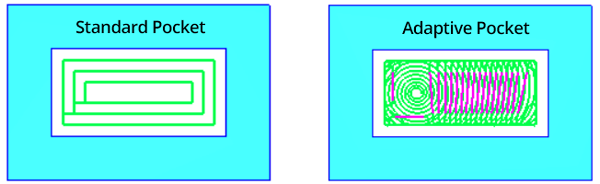
In the images above, you can see the path motion for traditional pocketing on the left and the Adaptive pocketing on the right.
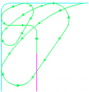
In this example, there are corners that need to be cleaned out. If we take a closer look at the path created, you can see how the toolpath is continually taking small passes and working its way into the corner of the workpiece.
Controlling the size of the curving motion is important. The larger the tool, the larger this radius must be to ensure tool engagement amount is maintained.
The curving motion is controlled in the BobCAD-CAM Adaptive strategies using the Minimum Curvature Radius value. Notice how the curvature of the path changes with this value in the following images.

When using One Way machining the adaptive path generated by BobCAD-CAM includes linkback moves that perform what we refer to as a Micro Lift if the distance is greater than 5x the tool diameter. In the following image, the Micro Lift move is displayed in the pinkish color.
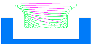
These link back moves are used to reposition the tool for the next pass across the material. The BobCAD-CAM systems will apply the Maximum Defined Cutting Feedrate value to these moves in the NC program. This allows the machine to run at a much higher feedrate for this motion, providing additional cycle time reduction.

BobCAD-CAM has provided CNC Software products to the global manufacturing industry for over 30 years. BobCAD-CAM software can be found to increase CNC productivity for many applications including educational and independent hobby home use. Products include machining technology for 2, 3, 4 & 5 Axis CNC Milling, Routing, Waterjet, Plasma and Laser machines as well as 2 Axis CNC Lathe. BobCAD-CAM also provides a variety of quality training products that include regional and online training classes or private sessions tailored to specific applications. Professional certification can be acquired as well as multi-tiered technical support solutions to their service customers.
Contact BobCAD-CAM today at 877-262-2231 or 727-442-3554.
References:
Resource 1
Resource 2
Resource 3
Resource 4
Resource 5
Resource 6
Resource 7
Resource 8
Resource 9
You’re one click away from subscribing to BobCAD’s YouTube channel. Click the link below for tips, how-tos and much more!