Questions? Call Us to speak with a CAD CAM Pro!
In the intricate world of CAD/CAM machining, precision is paramount. Every step, from initial setup to simulation, plays a pivotal role in ensuring flawless execution. Let’s embark on a comprehensive exploration of BobCAD-CAM’s machine setup and simulation features, unraveling their intricacies and unveiling their potential.
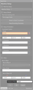
Machine Setup: Laying the Foundation
The machine setup dialog serves as the bedrock of your machining endeavors, offering a multitude of options to fine-tune your operation:
| Zero by UCS | Zero by Location | Work Offset # | Work Offset XYZ | Clearance |
 |
 |
 |
 |
 |
.
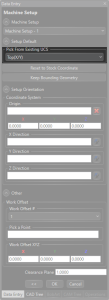
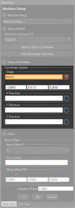
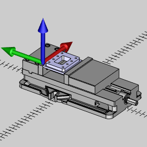
Machine Setup – Zero Location:
Defined using the World Coordinate System in the graphics area, the zero location can be set via an existing UCS, a specific point, or defined coordinates. The difference between the WCS and the Machine Setup can be used to define the Work Offset XYZ value to set the position of the workpiece on the simulated machine.
| Machine Setup | Machine Setup vs WCS |
 |
 |
.
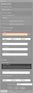
Machine Setup – Work Offset #:
Specifies the work offset number in the output code. By default, unless defined otherwise in the post, a value of 1 will output G54, two will output G55, and so on.
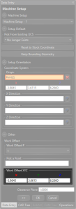
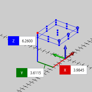
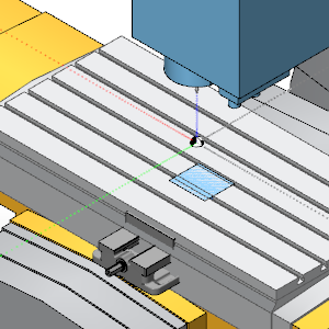
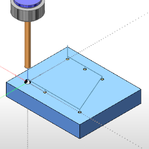
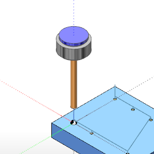
Machine Setup – Work Offset XYZ:
This value is only important if you want to view the stock/workpiece in the correct location, in relation to the machine, in the simulation. When working with basic 2 Axis programs on Laser, Plasma, Waterjet, Router machine, this may not be a concern. In those cases, feel free to disregard this value, and hide the machine when simulating. However, this value becomes important when ensuring jobs are within machine limits, and even more so on multiaxis machines when crashing between machine components and fixturing becomes a concern.
| Work Offset XYZ = X0, Y0, Z0 | Work Offset XYZ = X-3.98, Y3.61, Z6.26 |
 |
 |
.
Machine Setup – Clearance:
Defines the clearance height relative to the top of the stock, a critical parameter for safe tool movements.
Simulation: Navigating the Digital Terrain
As we delve into the realm of simulation, a plethora of tools awaits, each designed to empower and enlighten:
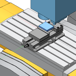
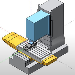
Simulation – Focus:
Toggle your focus between the machine, workpiece/stock, or tool, providing nuanced insights into different facets of the machining process.
| Machine | Workpiece/Stock | Tool |
 |
 |
 |
.
Simulation – Tabs:
Dive deep into analysis with a myriad of tabs catering to various aspects of stock removal and machining dynamics:
-
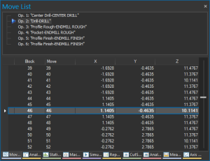
- Move List: Track individual operation movements.
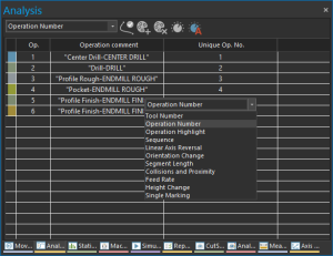
- Analysis: Monitor operation assignments, feed rates, and height changes.
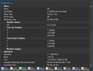
- Statistics: Delve into move tracking, feedrates, machining time, and more.
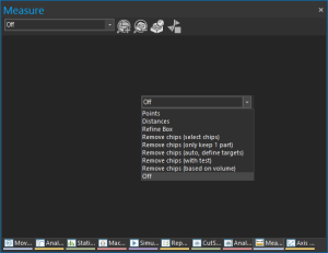
- Measure: Gauge stock dimensions and manage chip removal.
| Move List | Analysis | Statistics | Measure |
 |
 |
 |
 |
.
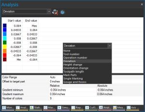
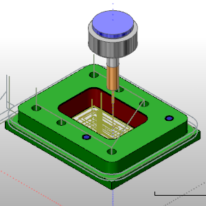
- Deviation Report: The Analysis tab has a many helpful aspects, and one of the most helpful is undoubtedly the Deviation report. This allows you to compare the assigned workpiece to the resulting stock to visualize remaining stock and gouges quickly and intuitively. In the image below you can see we’ve ignored a couple holes, which is clear in blue, and added a negative allowance on the walls of the inner pocket which present as a clear gouge in red.
| Deviation | Deviation result |
 |
 |
.
Conclusion
In the intricate dance of CAD/CAM machining, mastery of machine setup and simulation is non-negotiable. With BobCAD-CAM’s robust features at your fingertips, you’re equipped to navigate the digital terrain with confidence and precision. Embrace these tools, delve into their depths, and unleash the full potential of your machining prowess.
Questions? Call Us to speak with a CAD CAM Pro!


Leave a Reply